

Electropneumatic equipment of a vehicle
- Summary
- Abstract
- Description
- Claims
- Application Information
AI Technical Summary
Benefits of technology
Problems solved by technology
Method used
Image

Examples
Embodiment Construction
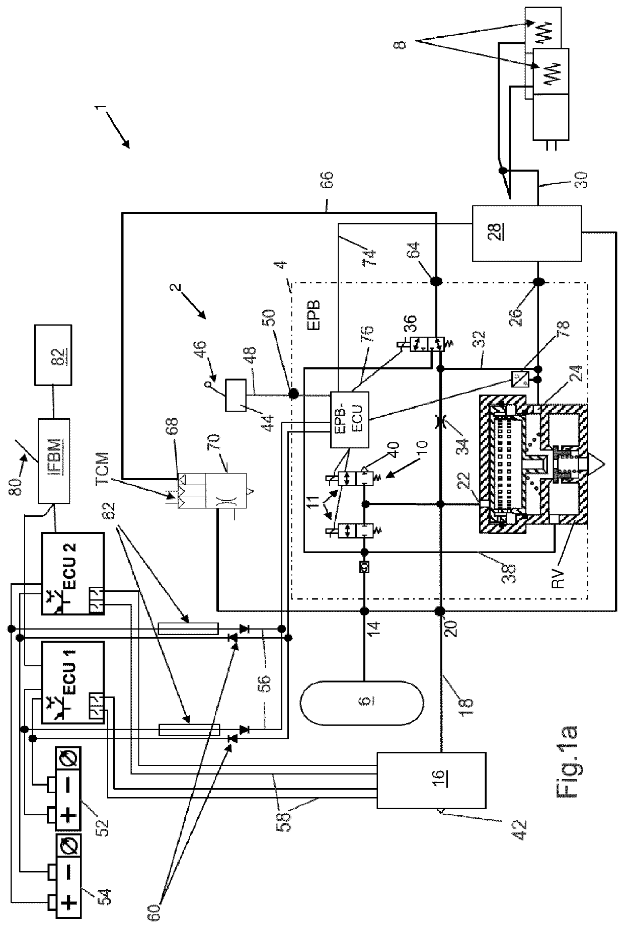
[0112]FIG. 1a shows a schematic circuit diagram of an exemplary embodiment of electropneumatic equipment 1 according to the invention. The electropneumatic equipment 1 may be part of a heavy utility vehicle as a tractor vehicle of a tractor-trailer combination and comprises an electropneumatic brake device made of an electropneumatic parking brake device 2 and an electropneumatic service brake device, which is here, for example, an electronically regulated service brake device (EBS) and is arranged on the tractor vehicle.
[0113]The electropneumatic parking brake device 2 comprises an electropneumatic parking brake control device EPB, which may have a separate housing 4, a compressed air supply 6, and a pneumatic spring-type brake cylinder 8. The electropneumatic parking brake control device EPB has an electronic parking brake control unit EPB-ECU and a first valve device 10, here made up of an inlet / outlet solenoid valve combination 11 and a relay valve RV pressure controlled thereby...
PUM
 Abstract
Description
Claims
Application Information