Motor actuator having simplified interfitting connection

a technology of interconnection and motor actuator, which is applied in the direction of couplings, instruments, mechanical equipment, etc., can solve the problems of high cost, high cost, and complex and costly manufacturing process for manufacturing each interconnection portion with a high degree of accuracy

Inactive Publication Date: 2001-08-09
ASMO CO LTD
View PDF0 Cites 8 Cited by
  • Summary
  • Abstract
  • Description
  • Claims
  • Application Information

AI Technical Summary

Problems solved by technology

However, in the above-described interfitting structure used for the above motor actuator, a complicated and costly manufacturing process is required for manufacturing each interfitting portion with a high degree of accuracy.
As a result, it is difficult to maintain a hi...

Method used


Image

  • Motor actuator having simplified interfitting connection
  • Motor actuator having simplified interfitting connection
  • Motor actuator having simplified interfitting connection

Examples


Embodiment Construction

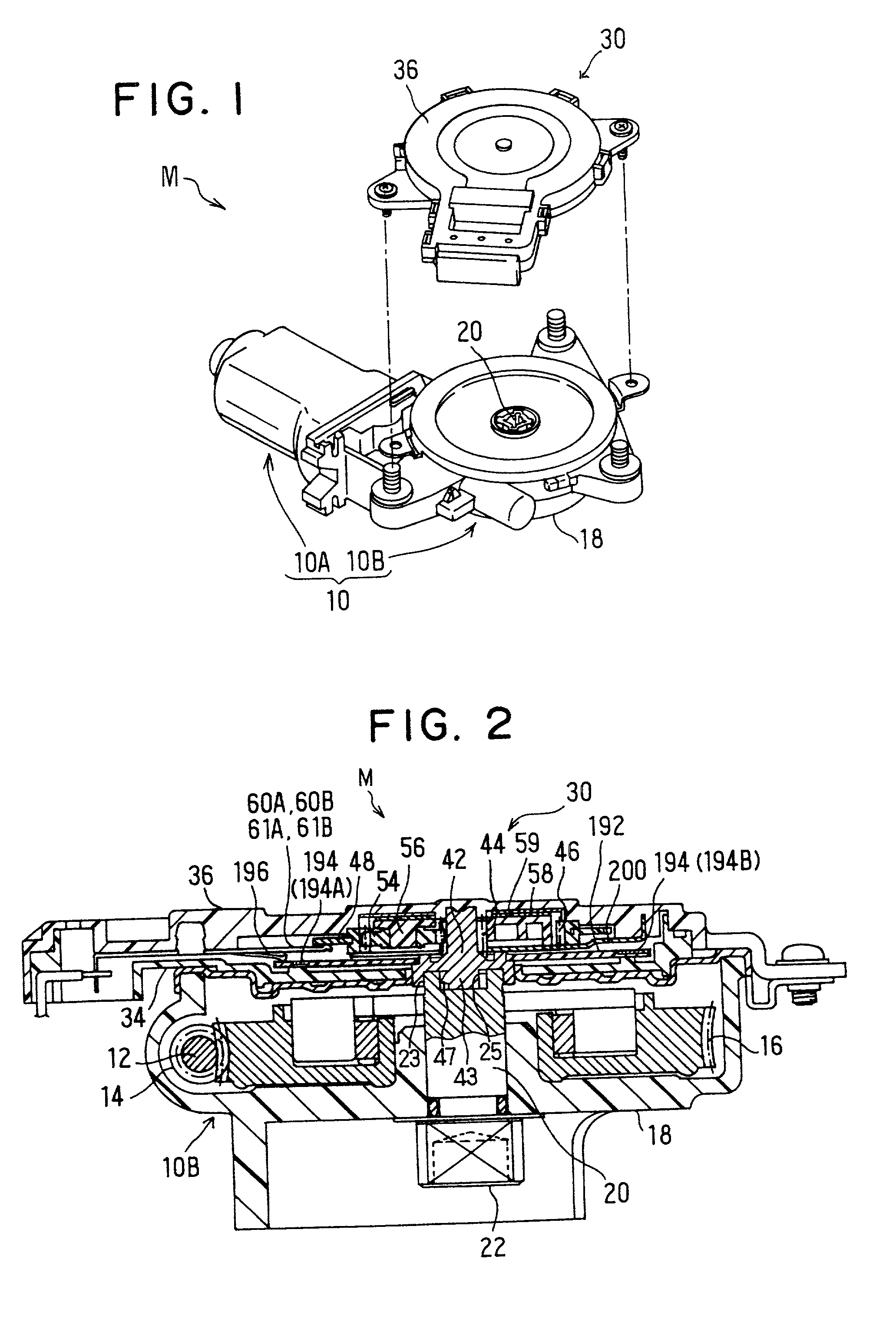
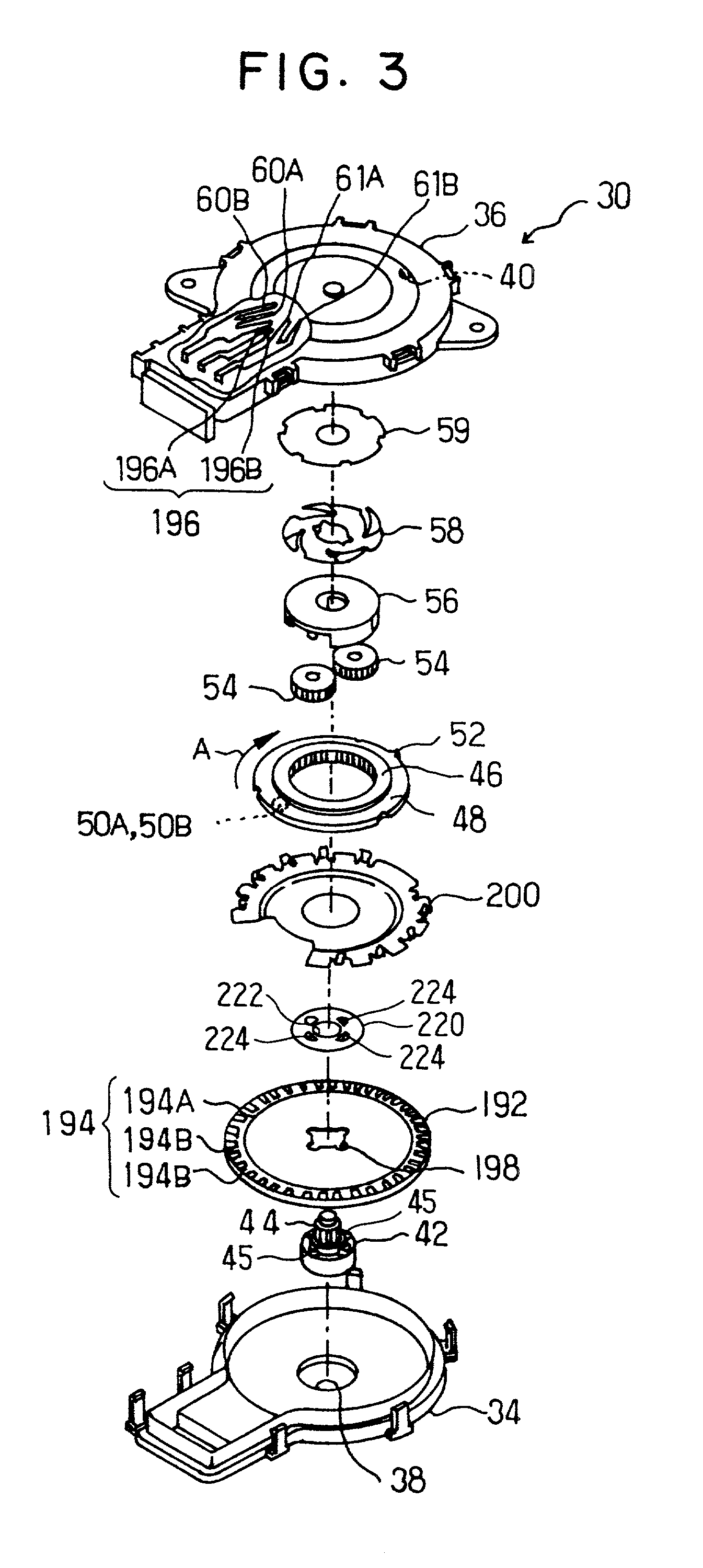
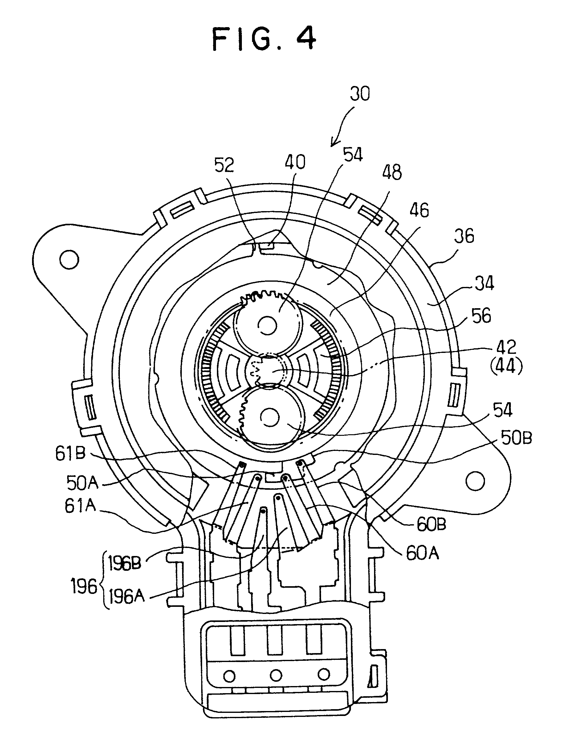
[0019] As shown in FIGS. 1 and 2, a motor actuator M according to an embodiment of the present invention includes a motor 10 and a position detector 30.

[0020] The motor 10 includes a motor portion 10A and a gear portion 10B connected with each other. A rotation shaft 12 of the motor portion 10A extends into the gear portion 10B, and a worm gear 14 is provided at a top end of the rotation shaft 12. The worm gear 14 is meshed (engaged) with a rotation gear wheel 16 disposed in the gear portion 10B.

[0021] A motor output shaft 20 of the rotation gear wheel 16 is rotatably supported by a cover 18 of the gear portion 10B. When the motor portion 10A is driven to rotate the rotation shaft 12, a rotational force of the rotation shaft 12 is transmitted to the rotation gear wheel 16 through the worm gear 14 to rotate the motor output shaft 20. An output fitting portion 22 is provided at a distal end of the motor output shaft 20 and is connected to a driving portion of a window regulator (not s...


PUM


Abstract

In a connection between a motor and a position detector that together constitute a motor actuator, a connection shaft of the position detector is engaged with an outer peripheral surface of a motor output shaft, and a shaft portion of the connection shaft is engaged with an inner peripheral surface of the motor output shaft. Furthermore, radial recesses are provided to be radially outwardly recessed from the inner peripheral surface of the motor output shaft, and one of radial recesses of the motor output shaft engages with a single radial projection of the shaft portion of the connection shaft. Thus, the motor output shaft and the connection shaft are non-rotatably connected with each other, readily accurately.

Description

[0001] This application is related to and claims priority from Japanese Patent Application No. 2000-27519 filed on Feb. 4, 2000, the contents of which are hereby incorporated by reference.[0002] 1. Field of the Invention[0003] The present invention relates to a motor actuator used, for example, in a power window device that moves a window glass of a vehicle door up and down or in a sunroof device that moves a sunroof panel forward and backward.[0004] 2. Description of Related Art[0005] Generally, a power window device and a sunroof device have a motor as a drive source. For instance, JP-A-8-29114 and JP-A-9-236431 respectively disclose a motor actuator having a feature capable of detecting a rotational position of an output shaft of such a motor, i.e., a position of a window glass or a sunroof panel.[0006] The above-disclosed motor actuator has a motor and a position detector that are connected with each other. The position detector includes a planetary gear train unit, a switch por...

Claims


Application Information

Patent Timeline
IPC IPC(8): G01D5/245H02K7/116H02K11/00
CPCH02K7/1166H02K11/0015H02K11/21H02K7/116
Inventor YAMAMURA, KENGO
Owner ASMO CO LTD
Why Eureka
Try Eureka