Machine component monitoring, diagnosing and selling system

a technology for monitoring systems and components, applied in the direction of instruments, nuclear elements, static/dynamic balance measurement, etc., can solve the problems of increasing the maintenance cost of facilities, affecting the quality of the system,

Inactive Publication Date: 2002-01-31
NTN CORP
View PDF10 Cites 97 Cited by
  • Summary
  • Abstract
  • Description
  • Claims
  • Application Information

AI Technical Summary

Benefits of technology

[0013] According to the present invention, the influence signal resulting from passage of the rolling elements occurring in the machine component is detected by one of the sensors which is provided in the vicinity of such machine component. In other words, the sensor employed in the system of the structure described above is used to detect strains, change in load, vibration or the like. The influence signal is any signal that is generated in the machine component as a result of passage of the rolling elements, which may represents, for example, strains, change in load, vibration and others produced at a predetermined side of the machine component. In the event of the presence of a defect in the machine component, the influence signal contains a signal component brought about by the defect. Each of the determining units determines the presence or absence of an abnormality and / or the status of lifetime or the like of the machine component according to a predetermined process set-up condition in reference to the influence signal that has resulted from passage of the rolling element, which influence signal contains the defect signal component. A result of determination is collected by the control means. In this way, since the status of any of the machine components can be grasped, no spare period need be taken sufficiently long and the time span between the succeeding replacement times can be prolonged. Also, in the event of the incipiency of the abnormality in the machine component, the abnormality can be quickly detected and counteracted upon before the machine is scrammed.
[0014] Also, since the control means is used to collect respective results of determination performed by the determining units, monitoring of the presence or absence of an abnormality and / or the lifetime of any of the machine components can be accomplished with a simplified construction, at a low cost, accurately and efficiently.
[0015] Since each of the determining units is connected with the plural sensors so that the machine component associated with the respective sensor can be determined, a minimized number of the determining units is sufficient to perform determination with respect to an increased number of the machine components. Where the machine components used in a particular machine system are of the same specification, each of the determining units can process any of the output signals from the various sensors according to the same process set-up condition. Also, since the determining units each connected with the plural sensors are connected to the common control means, the results of determination performed by a considerable number of the determining units, respectively, can be collected by the sole control means. For this reason, for the machine system provided with a considerable number of the machine components, the single control means is sufficient to extensively monitor those machine components with high efficiency.

Problems solved by technology

The roll support bearings, particularly, rolling roll support bearings used in a continuous casting machine are used under a relatively large load and at an elevated temperature and, thus, under severe operating conditions.
Since sudden interruption of the operation of the plans as a result of an abnormality occurring in some of the support bearings would highly result in a considerable loss, the support bearings are regularly replaced at intervals of a few months.
However, since during the routine replacement it often occurs that some of the support bearings that can still be usable are replaced in anticipation of safety, the support bearings are necessarily used uneconomically, resulting in increase of the cost of maintenance of the facilities.
Accordingly, attempts have been made to use vibrations sensors to monitor the status of the lifetime of each support bearing, but since the number of the support bearings used is considerable, a relatively high cost is incurred in monitoring those support bearings.
However, with a diagnosing instrument used in the iron work plant or the paper making plant and also with the technician in the plants, a problem has been encountered that an accurate diagnosis is difficult to achieve.
In the event of occurrence of an abnormality resulting from an erroneous diagnosis, a loss such as sudden scramming of the plant would occur.
Employment of diagnosing instruments and / or technicians in the iron work plant or the paper making plant is indeed uneconomical since the diagnosing instruments and / or the technicians sometimes lead to unnecessary expenditure.
Also, if after the machine components, i.e., the bearings have been diagnosed at the iron work plant or the paper making plant and then the attendant worker consults with a sales representative sent from the bearing manufacturer, a relatively large amount of time and labor are required and, because of it, it often occurs that delivery of the ordered bearing will be delayed.
On the other hand, even the bearing manufacturer would be required to store a large amount of bearings in anticipation of varying orders and, also, has to employ personnel for sales activities while requiring a relatively large amount of expenditure for personnel shift.
While it is generally recognized that if too many sensors are connected with one determining unit, not only must the determining unit have a high speed processing performance, a relatively long wiring would be required between the sensors and the determining unit particularly in the case of the large scale machine system, resulting in a problem in transmission of the sensor signal.
If in the machine component which ought to rotate at the same number of revolutions a difference occur in number of revolution, it is clear that the machine component of which rotation is retarded has an abnormality in any way whatsoever.
The determiner abnormality includes, for example, a communication abnormality occurring in communication between the control means and any one of the determining units, a parameter abnormality which occurs when a process set-up condition for setting a parameter to the determining unit is improper, a function abnormality occurring in a central processing unit forming the determining units and so on.
In the machine system, it is often experienced that the wiring is difficult to achieve and / or tends to constitute an obstruction.
If diagnosis of the lifetime of each of the machine components (1) were to be performed by a machine, it often occurs that not only is a relatively large amount of information needed, but also determination would be impossible in a special case.

Method used


Image

  • Machine component monitoring, diagnosing and selling system
  • Machine component monitoring, diagnosing and selling system
  • Machine component monitoring, diagnosing and selling system

Examples


Embodiment Construction

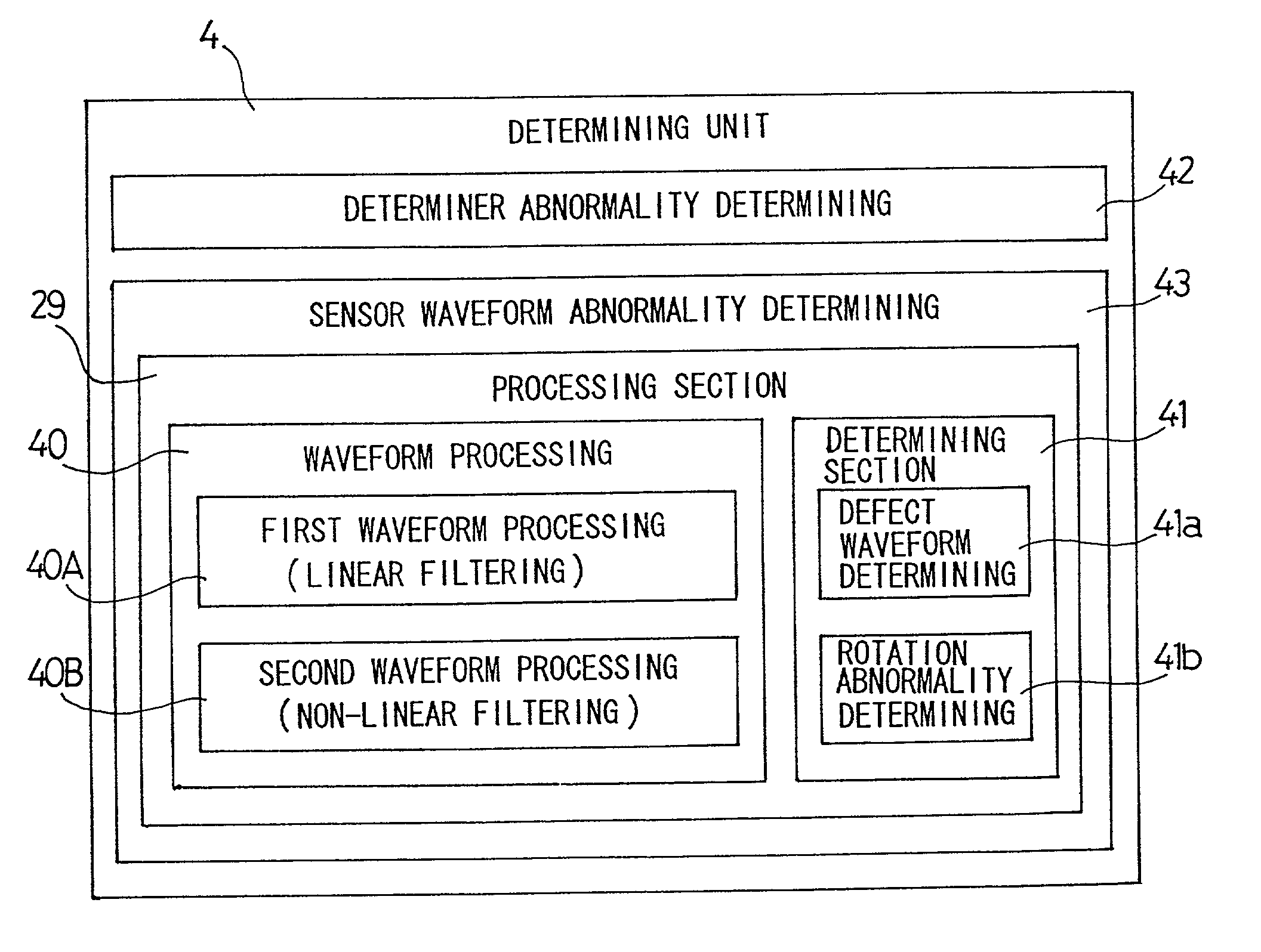
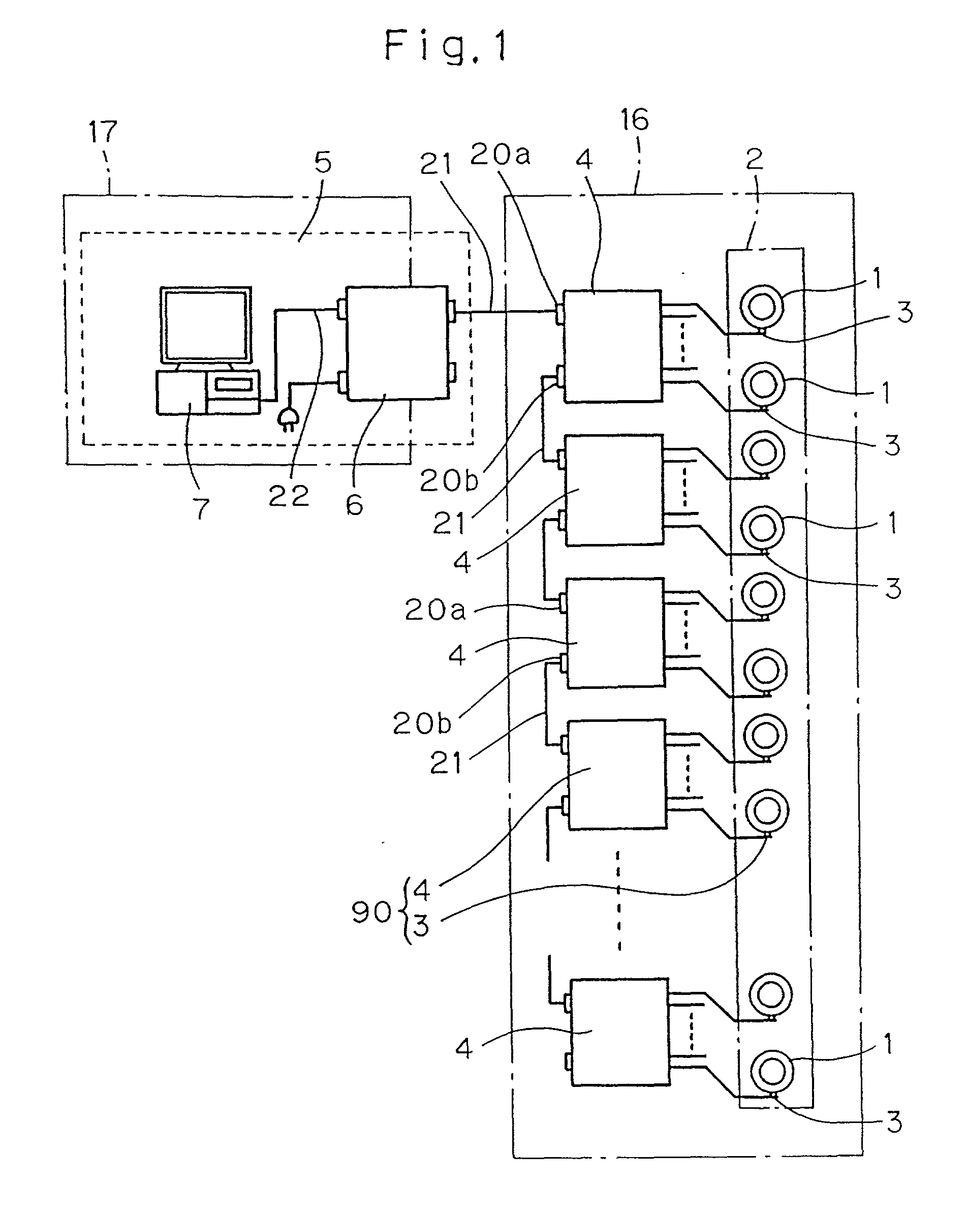
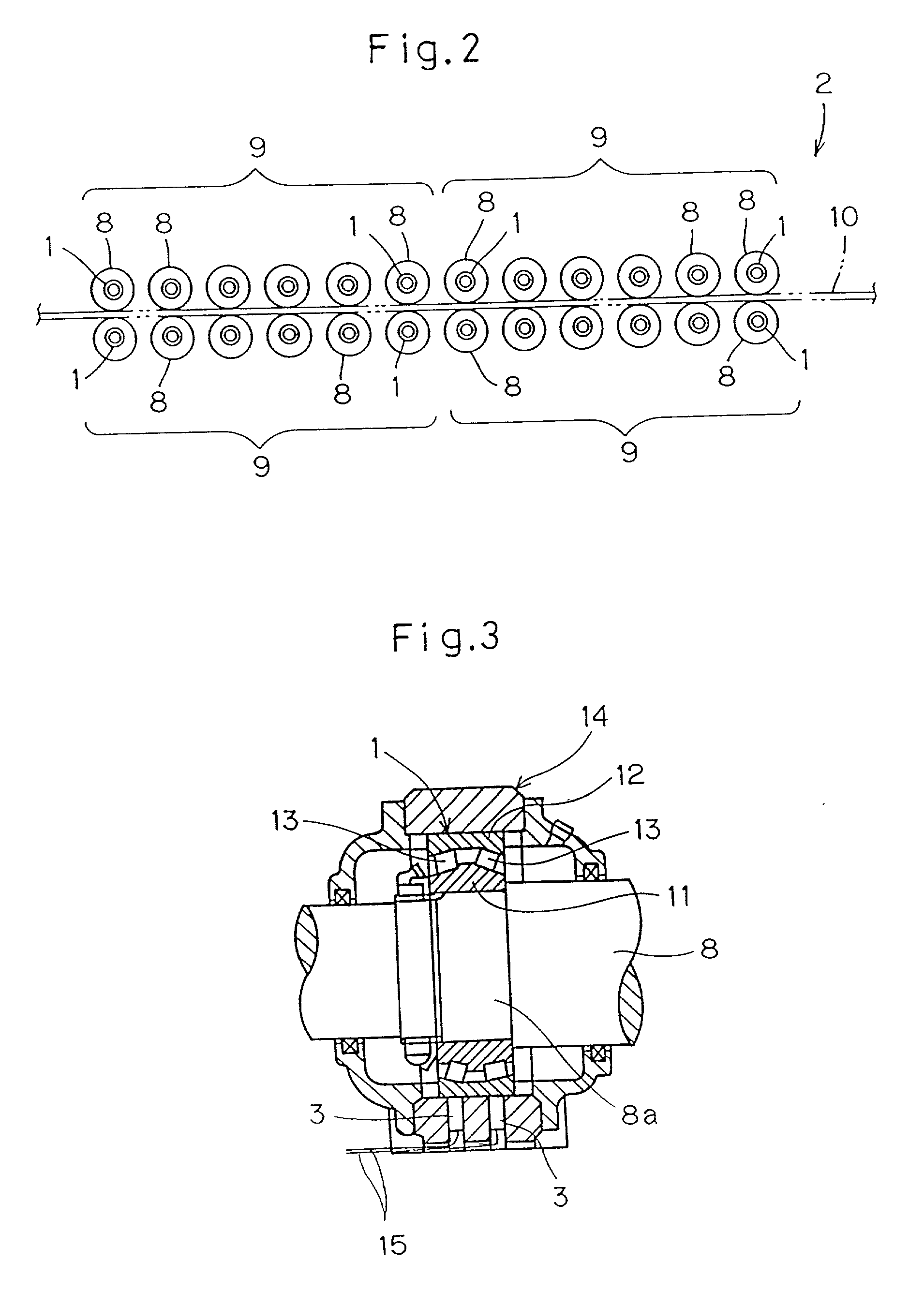
[0133] Preferred embodiments of the present invention will now be described with reference to the accompanying drawings. Shown in FIG. 1 is a monitoring system embodying the present invention, which is used for monitoring a plurality of machine components 1 employed in a machine system 2 and including rolling elements. This monitoring system includes a plurality of determining units 4 each electrically connected with a plurality of sensors 3 and a control means 5 common to and electrically connected with the determining units 4. The sensors 3 are installed one for each of the machine components 1 and positioned in the vicinity of the respective machine component 1. Each of the determining units 4 is operable in response to an output signal from the sensors 3 that are connected therewith to determine the status such as, for example, the presence or absence of an abnormality and / or the lifetime of the machine components 1, associated with such sensors 3, according to a predetermined p...


PUM


Abstract

A system for monitoring statuses such as presence or absence of abnormality and lifetime of a machine component such as, for example, a bearing having rolling elements includes a plurality of determining units 4 each connected with a plurality of sensors 3, and a control means 5 connected with the determining units 4. Each sensor is disposed on the machine component 1 of the associated rolling bearing for detecting an influence signal resulting from passage of the rolling element induced in the machine component 1. Each determining unit 4 determines according a process set-up condition the presence or absence of an abnormality, lifetime and others of the machine component 1 associated with the sensor 3 in reference to an output signal from such sensor 3. The control means 5 collects a result of determination performed by each determining unit 4. In this way, with a simplified structure, monitoring can be achieved at a low cost, precisely and efficiently.

Description

[0001] 1. Field of the Invention[0002] The present invention relates to a machine component monitoring system for monitoring statuses such as the presence or absence of an abnormality and / or lifetime of machine components employed in a machine system such as, for example, an iron work plant or a paper making plant that are equipped with such machine components each having rolling elements such as, for example, rolling bearings, constant speed joints or ball screw mechanisms, to a machine component monitoring and diagnosing system for enabling a manufacturer of the mechanical component to monitor and diagnosis at a remote location the statuses such as the presence or absence of an abnormality and / or lifetime of machine components each having rolling elements such as, for example, rolling bearings, constant speed joints or ball screw mechanisms that are employed in the machine system, and to a machine component monitoring, diagnosing and selling system for adding merchandise informati...

Claims


Application Information

Patent Timeline
Patent Type & Authority Applications(United States)
IPC IPC(8): G05B23/02
CPCG01M13/045
Inventor GOTOU, YASUHIROHAKAMATA, HIROYUKIAZUMA, MASATAKA
Owner NTN CORP
Why Eureka
Try Eureka