Tension control system for rod and bar mills

Inactive Publication Date: 2002-11-28
MORGAN CONSTR CO
View PDF0 Cites 15 Cited by
  • Summary
  • Abstract
  • Description
  • Claims
  • Application Information

AI Technical Summary

Problems solved by technology

In practice, however, maintaining the product under constant minimum tension has proven to be an elusive goal.
Accurate real time measurement of bar and rod velocities has not been possible with previously available technology, and reliable velocity calculations have been frustrated by the many constantly shifting variables that must necessarily be

Method used


Image

  • Tension control system for rod and bar mills
  • Tension control system for rod and bar mills
  • Tension control system for rod and bar mills

Examples


Embodiment Construction

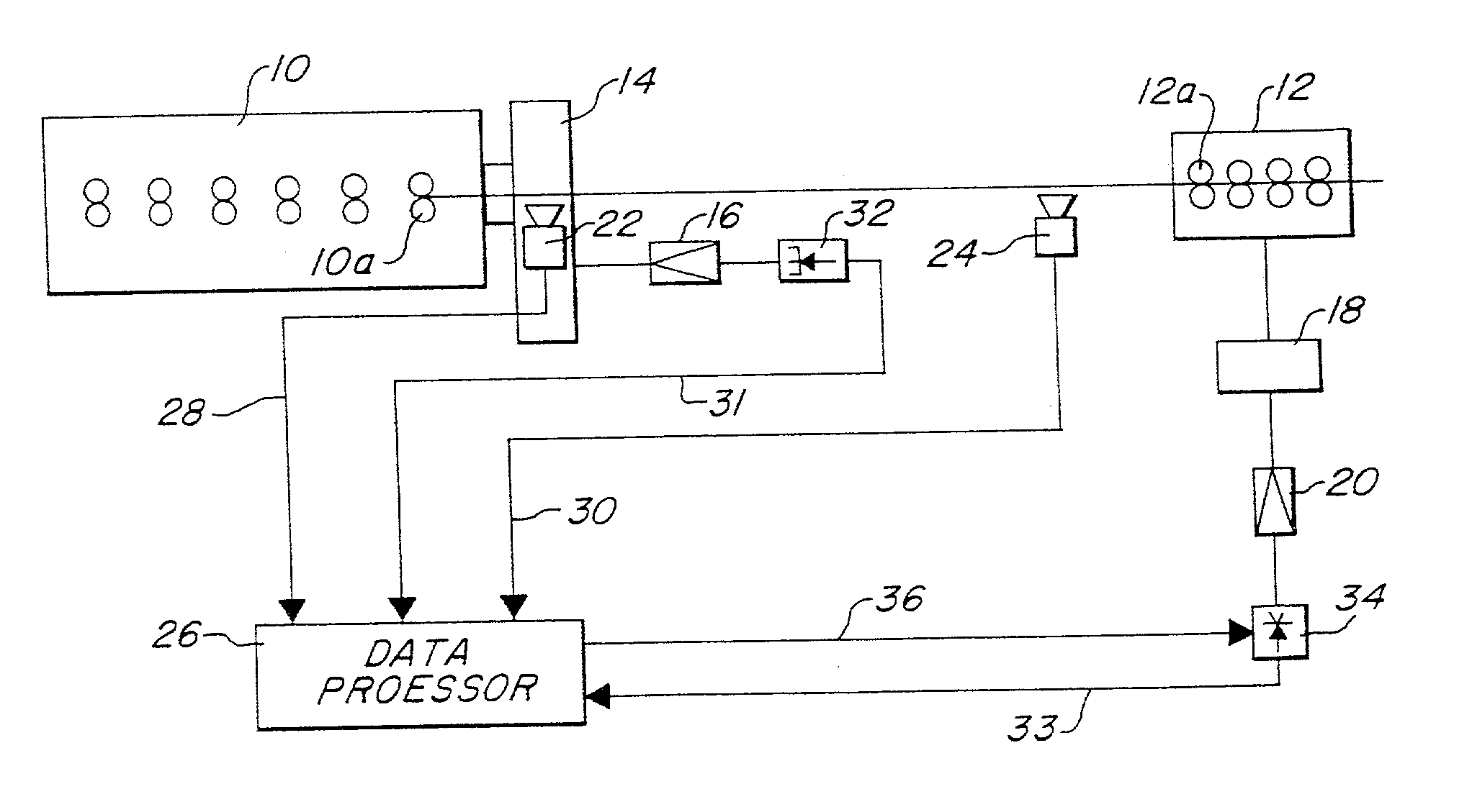
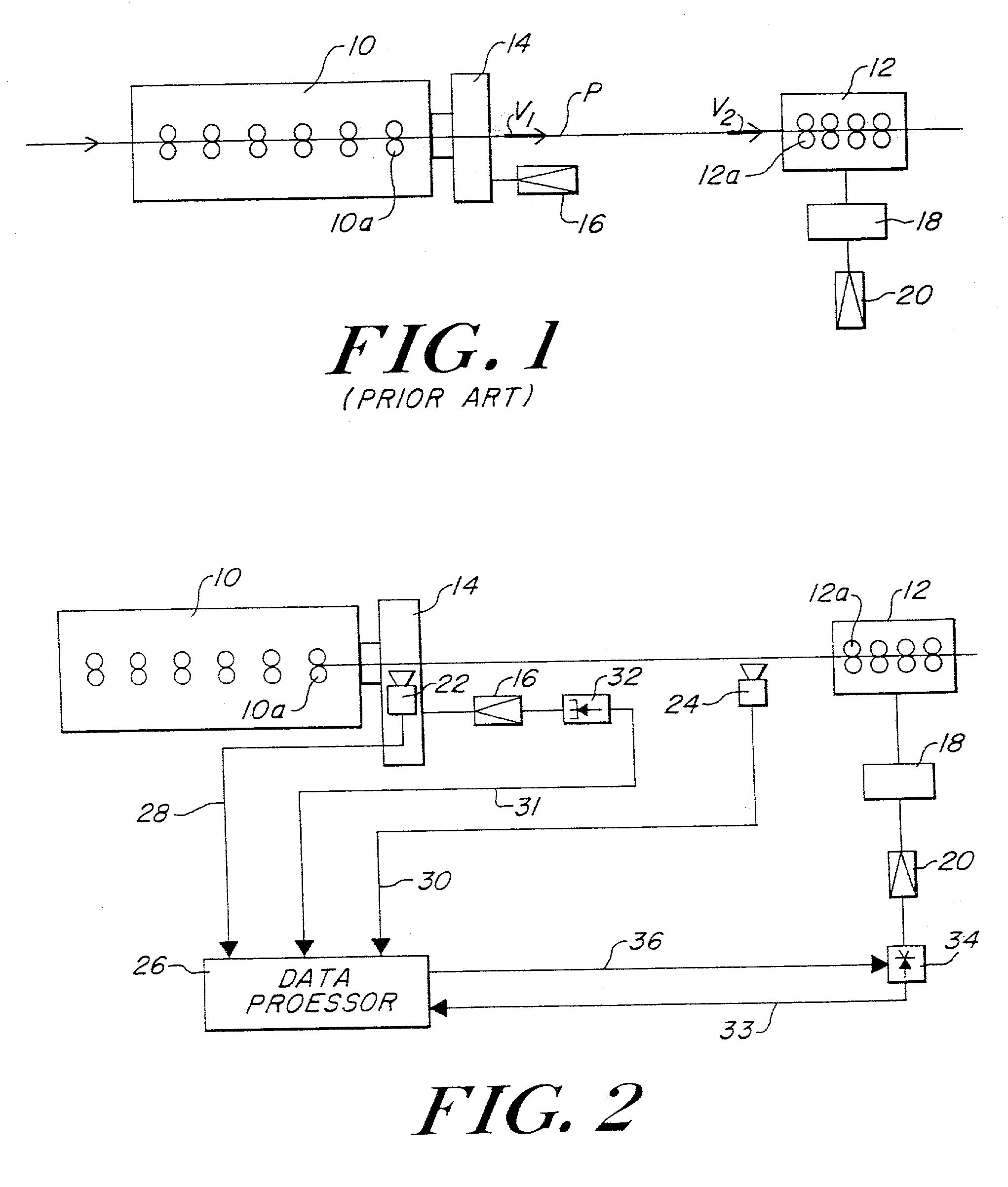
[0024] With reference to FIG. 2, it will be seen that a control system in accordance with the present invention includes first and second laser Doppler surface velocity gauges 22, 24 positioned, respectively, immediately following the last roll stand 10a of finishing block 10 and immediately preceding the first roll stand 12a of post finishing block 12. The gauges 22, 24 are preferably the LM-500-LSV-S2 model obtainable from American Sensors Corp. of Pittsburgh, Pa. U.S.A.

[0025] Gauge 22 continuously measures surface the velocity V.sub.1 of product exiting the last roll stand 10a of block 10, and gauge 24 continuously measures the surface velocity V.sub.2 of product entering the first roll stand 12a of post finishing block 12. A data processor 26 receives control signals generated by the gauges representative of product surface velocities V.sub.1 and V.sub.2 via lines 28, 30 and also receives signals via lines 31 and 33 representative of motor speeds from speed controllers 32, 34 as...


PUM

PropertyMeasurementUnit
Volumeaaaaaaaaaa
Electric potential / voltageaaaaaaaaaa
Speedaaaaaaaaaa

Abstract

A system is disclosed for controlling the tension in rod or bar products being rolled continuously in first and second roll stands independently driven by drive motors. A first surface velocity gauge is positioned at the delivery side of the first roll stand and a second surface velocity gauge is positioned at the entry side of the second roll stand. The first and second gauges are operative, respectively, to continuously measure and generate control signals representative of the exit surface velocity of the product exiting the first roll stand and the entry surface velocity of the product entering the second roll stand. Separately operable controllers are provided for varying the operating speeds of the roll stand drive motors. A data processor operates in response to the control signals generated by the velocity said gauges to determine in real time the differential between the product exit and entry surface velocities, and to generate command signals to the speed controller unit of at least one drive motor to vary the operating speed of that drive motor in order to maintain the differential between the product exit and entry surface velocities within a desired range.

Description

[0001] This application claims priority from provisional patent application Ser. No. 60 / 283,460 filed Apr. 12, 2001.BACKGROUND DISCUSSION[0002] 1. Field of the Invention[0003] This invention relates to control systems for controlling product tension between successive rolling units or roll stands in rod and bar mills.[0004] 2. Description of the Prior Art[0005] An example of conventional rod mill installation is diagrammatically depicted in FIG. 1, where a multi-stand finishing block 10 is followed along the mill pass line "P" by a multi-stand post finishing block 12. The finishing block 10 is driven via a gear unit 14 by a drive motor 16, and the post finishing block 12 is similarly driven via a gear unit 18 by a drive motor 20.[0006] In order to insure smooth passage of the product from block 10 to block 12, the velocity V.sub.2 of the product entering block 12 should be greater than the velocity V.sub.1 of the product exiting from block 10. This velocity differential insures that...

Claims


Application Information

Patent Timeline
IPC IPC(8): B21B1/18B21B37/52
CPCB21B37/52B21B1/18
Inventor RICHES, PAULRENZINE, FRANCOISSHORE, T. MICHAEL
Owner MORGAN CONSTR CO
Why Eureka
Try Eureka