Inflatable cuff for blood pressure measurement

Active Publication Date: 2005-01-20
OMRON HEALTHCARE CO LTD
View PDF6 Cites 19 Cited by
  • Summary
  • Abstract
  • Description
  • Claims
  • Application Information

AI Technical Summary

Benefits of technology

[0009] It is a disadvantage of the inventions disclosed in the references that noises produced by a relative slide motion of the shield plate and the bag for sensing the pulse waves, that is, by friction between the shield plate and the bag for sensing, cause inaccuracy in blood pressure measurement by propagating with signals output from the bag for sensing during slow deflation of the bag for pressing and the bag for sensing for blood pressure measurement because the shield plate is disposed outer side of the inner bag, that is, the bag for the pulse wave in the above references.
[0010] It is therefore an object of the present invention to provide an inflatable cuff for blood pressure measurement including an inflatable bag for pressing a body portion of a living subject and another inflatable bag for sensing a pulse wave, which is used for determining a definite blood pressure with reduced noises produced by friction.
[0011] To attain this object, the present invention provides the inflatable cuff for blood pressure measurement including: (1) a first inflatable bag which is inflatable to press an arterial vessel of a body portion of a living subject and stop flow of blood in the arterial vessel which the inflatable cuff is adapted to be wound around the body portion; (2) a second inflatable bag for sensing a pulse wave propagating along the arterial vessel, the second inflatable bag is supported by the inflatable cuff such that the second inflatable bag is located inside a dow steam-side portion of the f

Problems solved by technology

It is a disadvantage of the inventions disclosed in the references that noises produced by a relative slide motion of the shield plate and the bag for sensing the pulse waves, that is, by friction between the shield plate and the bag for sensing, cause inaccuracy in blood pressure measurem

Method used


Image

  • Inflatable cuff for blood pressure measurement
  • Inflatable cuff for blood pressure measurement
  • Inflatable cuff for blood pressure measurement

Examples


Example

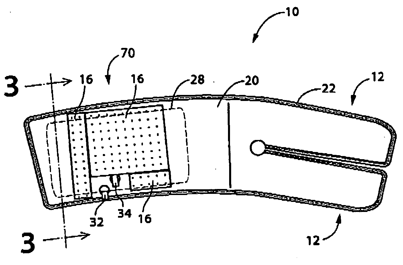
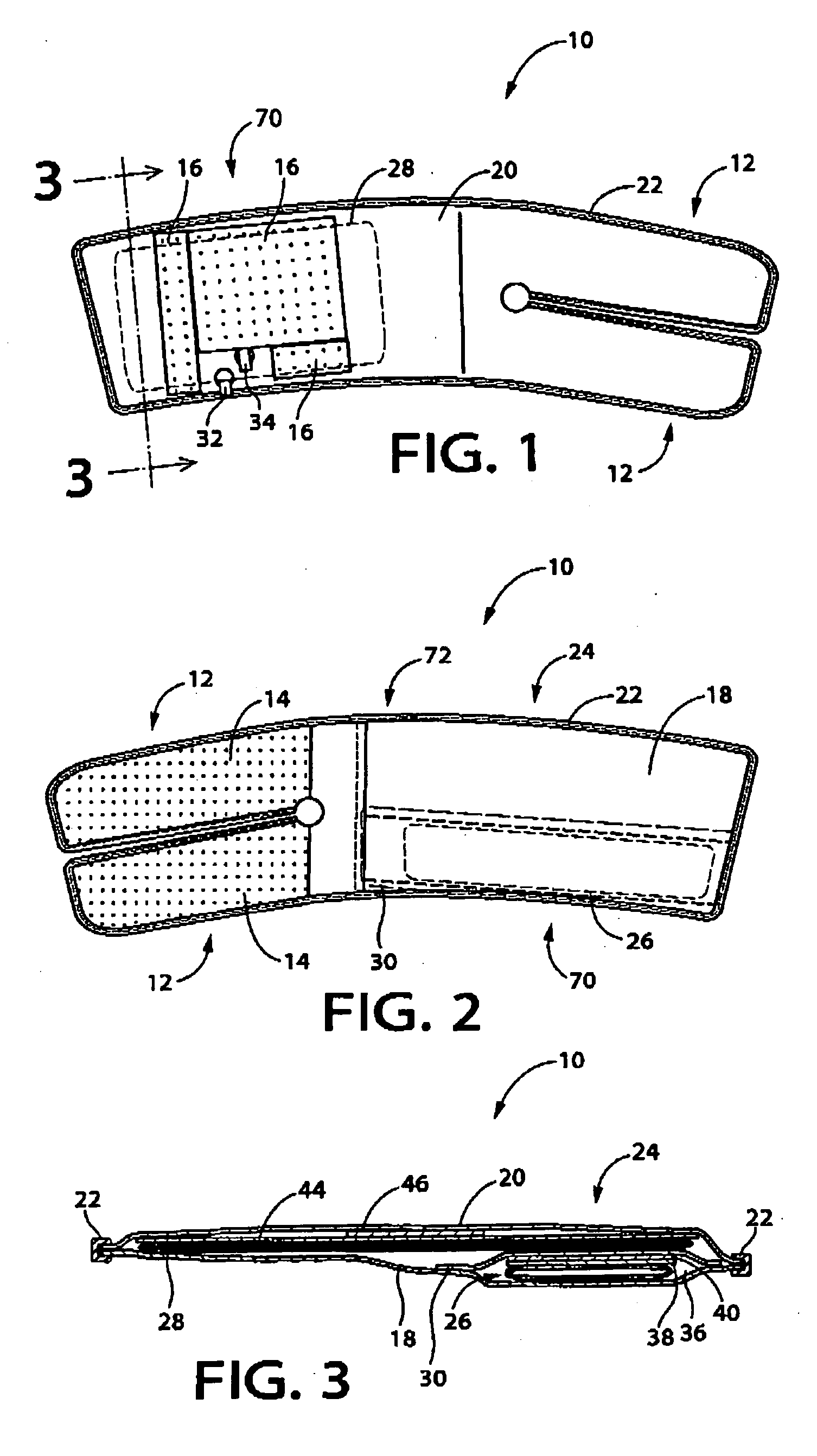
[0019] Hereinafter, there will be described an inflatable cuff for blood pressure measurement embodying the present invention, by reference to the drawings.

[0020] In FIG. 1, an inflatable cuff 10 which has a belt-like shape is about 14 cm in width and is slightly bent along a longitudinal direction to be formed an arch. The cuff 10 has two narrowed portions 12, 12 at one end in a longitudinal direction Each of the narrowed portions 12 is a half in width of the cuff 10 and has a fastener pad 14 on its inner surface, that is, a surface on a body portion side, and a main portion 70 of the cuff 10 also has fastener pads 16 on its outer surface, that is, a surface on the opposite side to the body portion side. The fastener pads 14 and 16 are fastened to each other, and the narrowed portions 12, 12 are unfastenably fixed to the main portion 70 at the fastener pads 14 and 16 with the cuff 10 wound around an ankle (not shown) and are on the most outside of the wound cuff 10. Consequently, ...


PUM


Abstract

An inflatable cuff for blood pressure measurement includes a first inflatable bag to press an arterial vessel of a body portion of a living subject for stopping blood flow; a second inflatable bag for sensing a pulse wave propagating along the arterial vessel, which is supported by the inflatable cuff such that the second inflatable bag is located inside a downstream-side portion of the first inflatable bag in the direction of the blood flows; a shielding member disposed between the first inflatable bag and the second inflatable bag so as to prevent an oscillation of the first inflatable bag from propagating to the second inflatable bag; and a slidable separating member disposed between the shielding member and the second inflatable bag so as to prevent generation of a noise caused by a slide contact of the shielding member with the second inflatable bag.

Description

BACKGROUND OF THE INVENTION [0001] 1. Field of the Invention [0002] The present invention relates to an inflatable cuff for oscillometric blood pressure measurement, which is adapted to be worn on a body portion of a living subject, and particularly to a cuff having a first inflatable bag for pressing the body portion and a second inflatable bag for sensing a pulse wave. [0003] 2. Description of Related Art [0004] In general, an oscillometric blood pressure measuring device determines a blood pressure based on pulse waves continuously received by the cuff wound around a body portion during a slow deflation to reduce a pressure by the cuff. [0005] The device adopts a static pressure of the inflatable bag as a systolic pressure, at a rising point of an envelope of amplitudes of the pulse waves, that is, a point where the amplitude of the pulse waves suddenly rises. [0006] The device may determine an indefinite systolic pressure with an indefinite rising point of the envelope of the am...

Claims


Application Information

Patent Timeline
IPC IPC(8): A61B5/022
CPCA61B5/02233
Inventor MIZUKOSHI, TOSHIYANISHIBAYASHI, HIDEO
Owner OMRON HEALTHCARE CO LTD
Why Eureka
Try Eureka