Display drive control device, for which drive method, electronics device and semiconductor integrated circuit

a control device and display drive technology, applied in static indicating devices, liquid/fluent solid measurement, instruments, etc., can solve the problems of increasing system load, changing the entire system control, and difficult to replace the display device without, so as to reduce system load, reduce system load, and easy change the power supply startup procedure

Active Publication Date: 2005-01-27
SYNAPTICS JAPAN GK
View PDF1 Cites 28 Cited by
  • Summary
  • Abstract
  • Description
  • Claims
  • Application Information

AI Technical Summary

Benefits of technology

[0007] It is therefore an object of the present invention to provide a display drive control device and a drive method thereof capable of easily changing a power supply startup procedure, complying with various display devices, and decreasing system loads by changing a procedure of generating voltages through the use of a sequence independent of the system control.
[0008] To achieve the above-mentioned purpose, the present invention automatically starts the power supply inside a display drive control device LSI. As possible functions, the liquid crystal display drive control device LSI should be able to control time waiting and variably set a sequence of voltage occurrences and time intervals. At the startup time, the microprocessor unit can start the power supply without time control. In this manner, the system's microprocessor unit can start the power supply without time control. This decreases system loads. Further, a procedure for starting the power supply can be changed easily. The display drive control device can be applied to diverse display devices.

Problems solved by technology

This increases system loads.
Further, changing a procedure for generating voltages may change the entire system control.
It has been difficult to replace the display device without changing the display drive control device such as the liquid crystal driver LSI and the like.

Method used


Image

  • Display drive control device, for which drive method, electronics device and semiconductor integrated circuit
  • Display drive control device, for which drive method, electronics device and semiconductor integrated circuit
  • Display drive control device, for which drive method, electronics device and semiconductor integrated circuit

Examples


Embodiment Construction

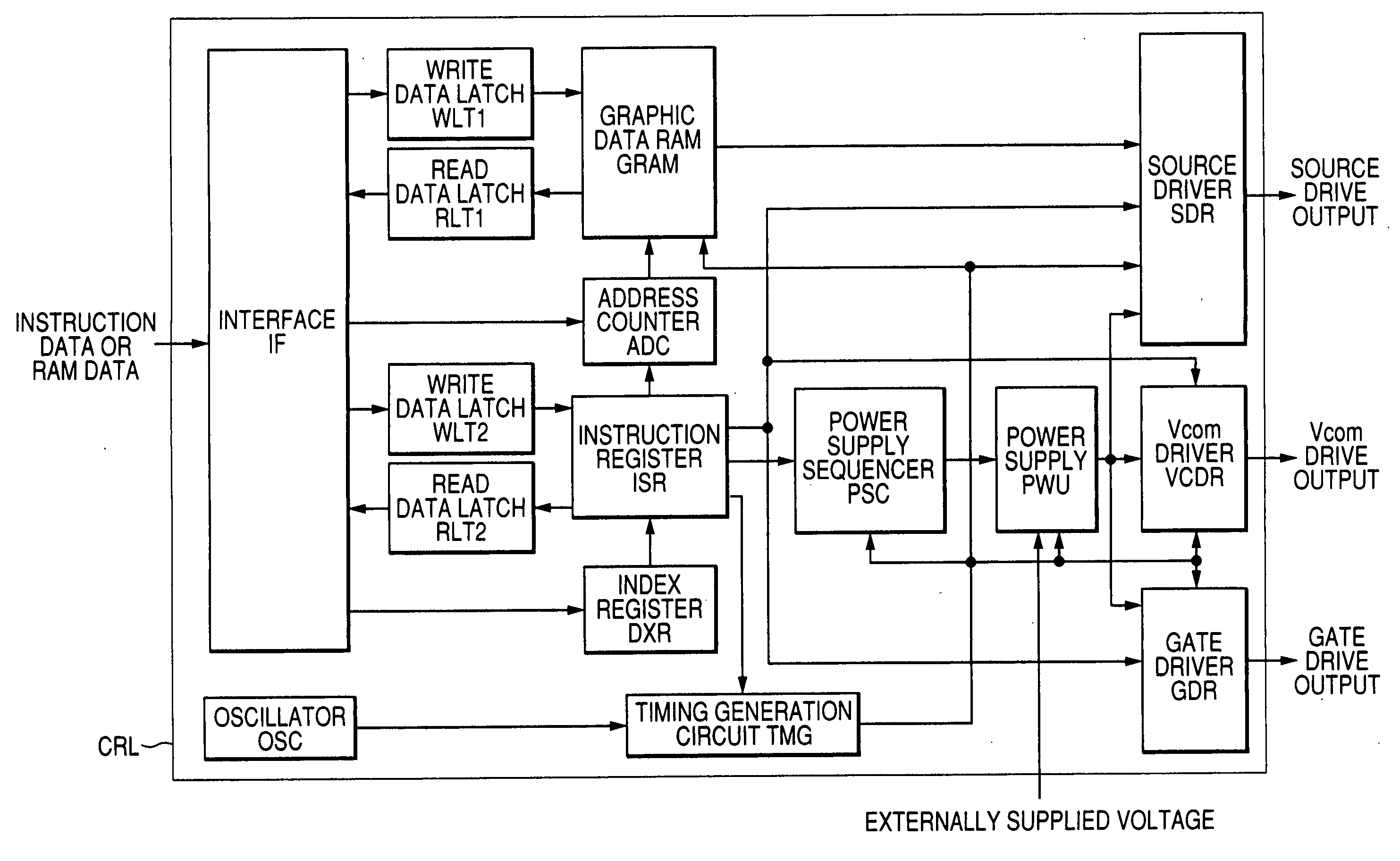
[0044] The following describes embodiments of the present invention applied to a cellular phone using the liquid crystal display as a display device in comparison with the art previously examined by the inventors. First, we will describe a power supply of the liquid crystal driver to be controlled by the power supply sequencer according to the present invention, and then the power control and effectiveness of the power supply sequencer. An embodiment is presented to describe the configuration of the power supply sequencer and a sequence to start and stop the power supply using the sequencer.

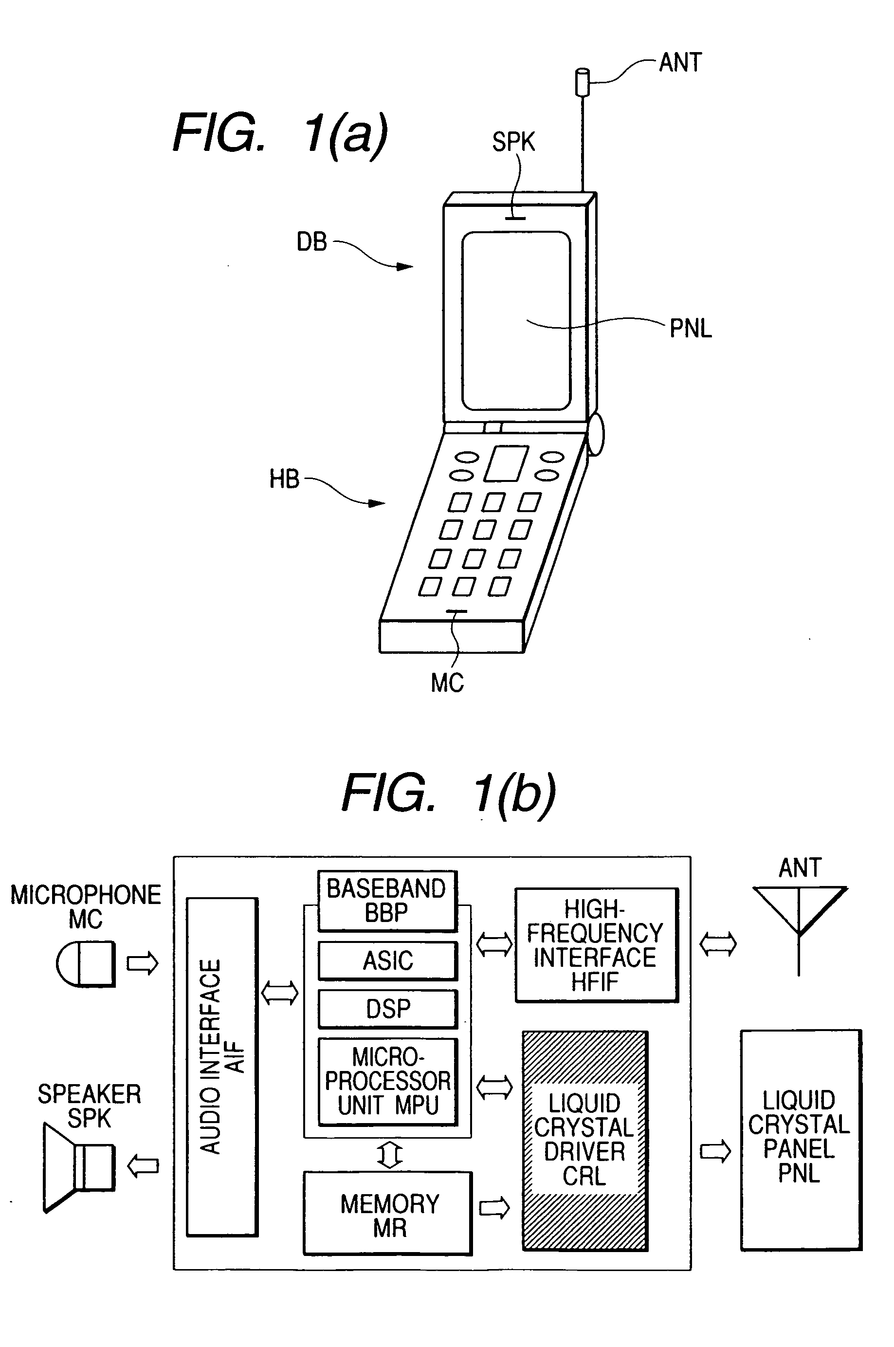
[0045]FIG. 1 is an explanatory diagram showing an ordinary cellular phone as an example of electronic devices to which the present invention is to be applied. FIG. 1(a) is an external view. FIG. 1(b) is a block diagram of the system configuration. As shown in FIG. 1(a), the cellular phone comprises a body section HB and a display section DB and is foldable at a hinge HNG. The surface of the body...


PUM

PropertyMeasurementUnit
voltageaaaaaaaaaa
voltagesaaaaaaaaaa
scan voltageaaaaaaaaaa

Abstract

It is aimed at being capable of easily changing a power supply startup procedure and complying with various display devices. A power supply circuit is provided between an instruction register of a liquid crystal driver and a power supply unit. The power supply unit is not directly supplied with a setting value registered to the instruction register from a microprocessor unit. The microprocessor unit writes setting values to the instruction register without need for the time axis. To turn on the power, the time is measured inside the power supply sequencer. Set values are sequentially input to the power supply unit. The instruction register should be also capable of registering an input timing.

Description

CROSS-REFERENCE TO RELATED APPLICATION [0001] The present application claims priority from Japanese patent application JP 2003-200249 filed on Jul. 23, 2003, the content of which is hereby incorporated by reference into this application. BACKGROUND OF THE INVENTION [0002] The present invention relates to a display drive control device and a drive method thereof. More specifically, the present invention relates to a display drive control device having a power supply circuit which generates a plurality of voltages from a single main power supply according to a specified procedure. [0003] A display drive control device having a so-called flat panel display device is used as a display device for electronic devices such as personal computers, television sets, cellular phones, and portable information terminals. In particular, liquid crystal displays are extensively used for cellular phones that are remarkably widespread in recent years. An electroluminescence display (organic or inorgani...

Claims


Application Information

Patent Timeline
Patent Type & Authority Applications(United States)
IPC IPC(8): G06F1/26G09G3/20G02F1/133G09G3/36G09G5/00
CPCG06F1/263G09G2330/026G09G2330/02G09G3/3696G09G3/36G02F1/133
Inventor MORITA, SHINSAKAMAKI, GOROTACHIBANA, TOSHIKAZU
Owner SYNAPTICS JAPAN GK
Why Eureka
Try Eureka