Force measurement cell

a technology of force measurement and force, which is applied in the direction of force/torque/work measurement apparatus, weighing apparatus details, instruments, etc., can solve the problems of high precision machining, increased cost, and ineffective protection mechanism, etc., and achieves low cost, low cost, and easy control of the gap

Inactive Publication Date: 2005-03-03
SHIMADZU CORP
View PDF3 Cites 3 Cited by
  • Summary
  • Abstract
  • Description
  • Claims
  • Application Information

AI Technical Summary

Benefits of technology

[0017] In the embodiments pertaining to the third and fourth aspects, displacement in the horizontal direction orthogonal to the respective axial direction is restricted concerning the lever mechanism (third aspect) or the beams of the Roberval mechanism (fourth aspect), respectively, and by forming a recessed part which sinks from the respective side surface of the block-like mechanism unit on both side surfaces orthogonal to the axial direction of the lever mechanism or the beams, and fixing a stopper on the fixed part of the block-like mechanism unit facing opposite the protruding part or recessed part with a prescribed gap opened, the displacement in the horizontal direction orthogonal to the axial direction of the lever mechanism or the beams can be restricted to the gap. Also, control of the gap is performed easily by controlling the depth of the recessed part, and in this case, although it is restricted only in a horizontal direction orthogonal to the axial direction in either case, a protective mechanism inside the force measurement cell is constructible with low cost.
[0018] According to an embodiment of the present invention, by applying simple machining to the block-like mechanism unit and also fixing a simple stopper by a screw, or the like, displacement of the lever mechanism or the beams of the Roberval mechanism is restricted in a required direction, and a protective mechanism inside the force measurement cell is constructible with low cost, and by combining with a protective mechanism outside the force measurement cell as exemplified in FIG. 7, damage to the movable parts inside the force measurement cell is preventable even under the action of vibrations during transport and strong impact loads, such as when falling.
[0019] A force measurement cell, comprising an internal protective mechanism restricting displacement in mutually orthogonal directions on the horizontal plane of a lever mechanism and protects these from vibrations during transport and impact loads, was realized based on a simple construction.

Problems solved by technology

While the protective mechanism having a stopper for restricting lever displacement in the vicinity of the electromagnetic force generator, which is commonly used in conventional electronic balances, functions effectively against comparatively small loads such as vibrations during transport, the protective mechanism may not function effectively against great impact loads, such as falling, because the displacement of the movable parts such as the lever is restricted in only one location.
However, in the technology disclosed in Patent Document 2, because a comparatively long bolt is screwed into the block-like mechanism unit and must be run through with a prescribed slight gap of about 0.1 mm with respect to through-holes formed on the lever mechanism and the beams of the Roberval mechanism in multiple locations in the longitudinal direction of the bolt, disadvantageously high precision machining is required both for the through-holes formed on the block-like mechanism unit and for the bolt.
Further disadvantageously, higher precision machining increase the cost.

Method used


Image

  • Force measurement cell
  • Force measurement cell
  • Force measurement cell

Examples


Embodiment Construction

[0027] Below, embodiments of the present invention are explained with reference to the accompanying drawings.

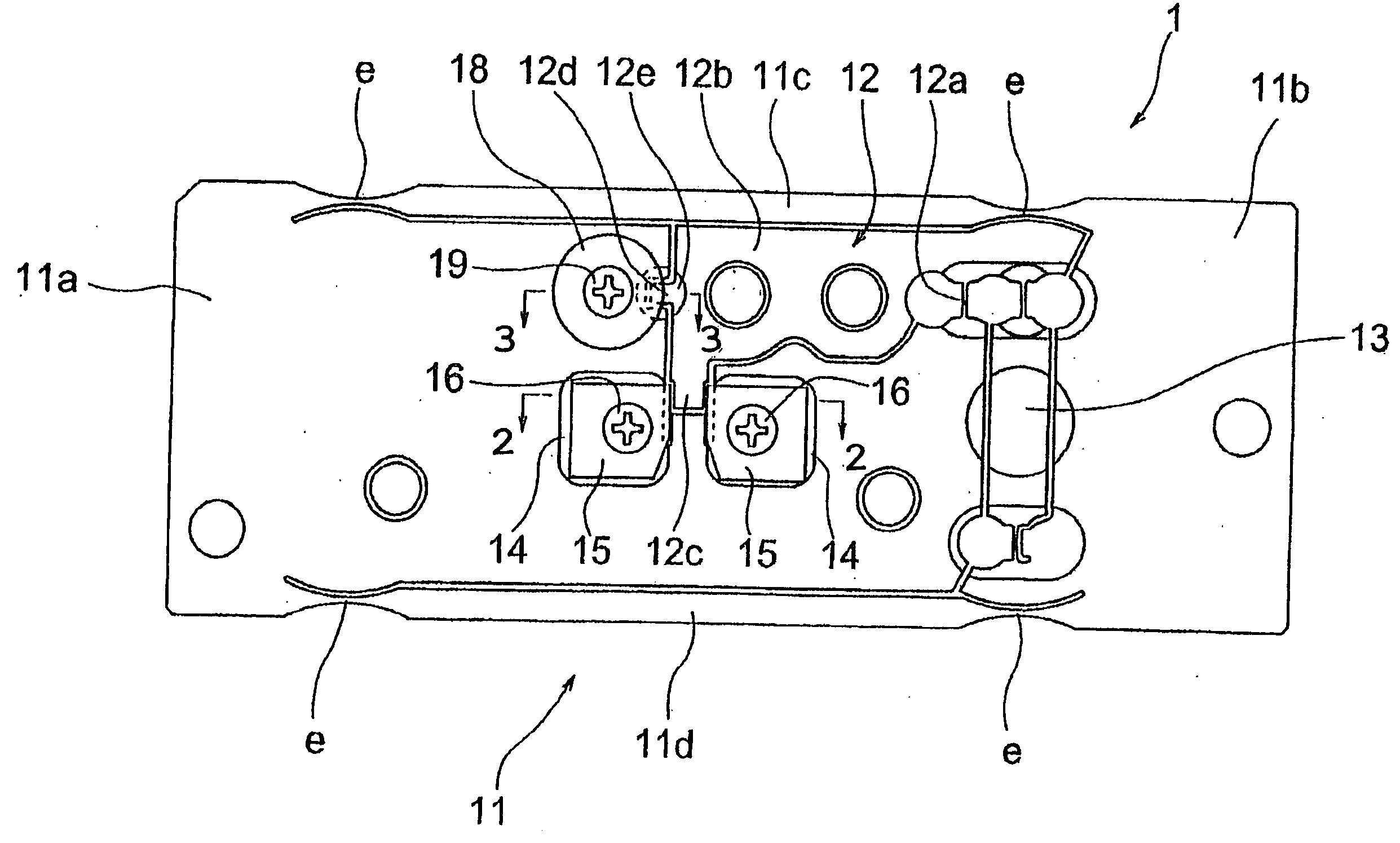
[0028] As depicted in FIG. 1, a block-like mechanism unit 1 constituting the force measurement cell is roughly hexahedral as a whole, and has a Roberval mechanism 11 and a lever mechanism 12, as well as a connecting part 13 connecting these, formed by cutting out a single piece of parent material by wire discharge cutting. The Roberval mechanism 11 has a structure in which a fixed column 11a and a movable column 11b are connected by two mutually parallel beams 11c and 11d, above and below, and flexible parts e are formed on both ends of each beam 11c and 11d. Also, the lever mechanism 12 consists mainly of a lever main unit 12b which tilts freely centered on a fulcrum 12a.

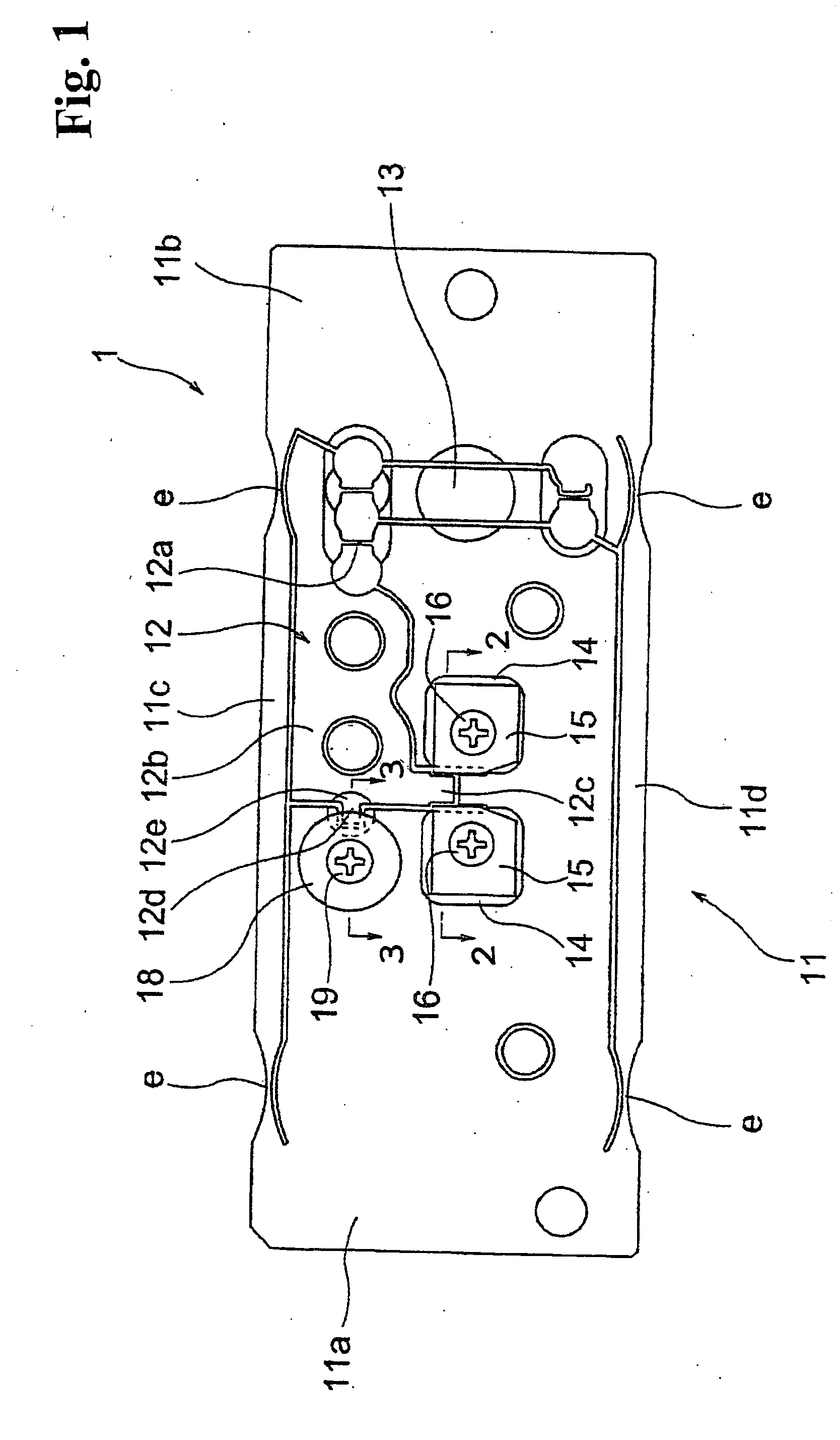
[0029] A protruding part 12c which protrudes downward is formed on the lever main unit 12b. On both sides of protruding part 12c, a total of four spot facing parts 14 cut into the respective surface are fo...


PUM

PropertyMeasurementUnit
flexibleaaaaaaaaaa
forceaaaaaaaaaa
force measurementaaaaaaaaaa

Abstract

A force measurement cell having a block-like mechanism unit includes a Roberval mechanism and a lever mechanism formed by cutting out a single piece of parent material. The Roberval mechanism has a fixed part and a movable part on which a measured force acts. A gapped part is formed on either the lever mechanism or the Roberval mechanism following the vertical direction orthogonal to the axial direction of the lever mechanism and the Roberval mechanism, respectively. In addition, a stopper for restricting displacement of either the lever mechanism or Roberval mechanism is fixed to the fixed part of the block-like mechanism unit facing opposite the gapped part with a prescribed gap opened in the axial direction of either the lever mechanism or the Roberval mechanism. Another embodiment, includes a recessed part sinking from a respective side surface of the block-like mechanism unit formed on both side surfaces.

Description

BACKGROUND OF INVENTION AND RELATED ART STATEMENT [0001] The present invention relates to a force measurement cell, and in particular, to a force measurement cell suitable for use in an electromagnetic force balance type electronic balance. [0002] An electromagnetic force balance type electronic balance generally has an electromagnetic force generator in which a movable coil is placed in a static electrical field generated by an electronic circuit, and the movable coil is attached to one end of a lever coupled with a tray. Also, the displacement of the lever due to a load to be measured on the tray is detected by a detector, the current flowing to the movable coil of the electromagnetic force generator is feedback-controlled such that the result of the detection always becomes zero, and the magnitude of the load to be measured is sought from the magnitude of the current necessary for zeroing the lever displacement. [0003] The tray normally is supported by a Roberval mechanism which ...

Claims


Application Information

Patent Timeline
Patent Type & Authority Applications(United States)
IPC IPC(8): G01G23/02G01G21/00G01G21/16G01L1/04G01L1/08G01L1/26
CPCG01L1/26
Inventor IIDUKA, ATSUSHI
Owner SHIMADZU CORP
Why Eureka
Try Eureka