Liquid crystal display device and electronic apparatus

a display device and liquid crystal technology, applied in non-linear optics, instruments, optics, etc., can solve the problem of narrow viewing angle in transmissive display mode, and achieve the effect of wide viewing angle, excellent display characteristics, and more stably regulating the alignment of liquid crystal molecules

Inactive Publication Date: 2005-04-28
SEIKO EPSON CORP
View PDF12 Cites 24 Cited by
  • Summary
  • Abstract
  • Description
  • Claims
  • Application Information

AI Technical Summary

Benefits of technology

[0030] Moreover, on the inner surface of the substrate on which the convex portions are formed, an opening is formed in each electrode at a position on the convex portion. In this case, since the electrode does not exist on the convex portion, the inclined direction of liquid crystal due to the shape of the convex portion is opposite to the direction of the electric lines of force. Therefore, the inclined direction of liquid crystal can be easily determin

Problems solved by technology

However, the related art transflective liquid crystal display device has a

Method used


Image

  • Liquid crystal display device and electronic apparatus
  • Liquid crystal display device and electronic apparatus
  • Liquid crystal display device and electronic apparatus

Examples


first exemplary embodiment

[0053] First Exemplary Embodiment

[0054] Hereinafter, exemplary embodiments of the present invention will be described with reference to the accompanying drawings. In the respective drawings, the reduced scale of each layer or each member is different from the actual scale because each layer or each member is scaled to be recognizable in the drawings.

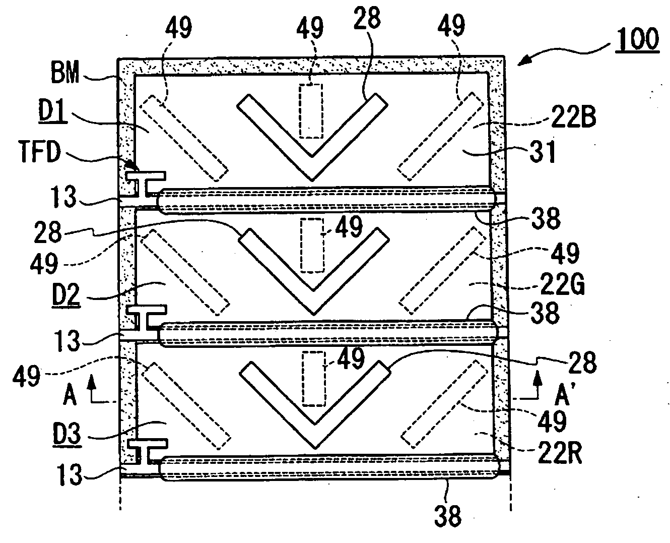
[0055] A liquid crystal display device of the present exemplary embodiment, which will be described below, is an active matrix liquid crystal display device in which thin film diodes (hereinafter, referred to as “TFDS”) are used as switching elements, and is particularly a transmissive liquid crystal display device capable of performing display using light emitted from a backlight.

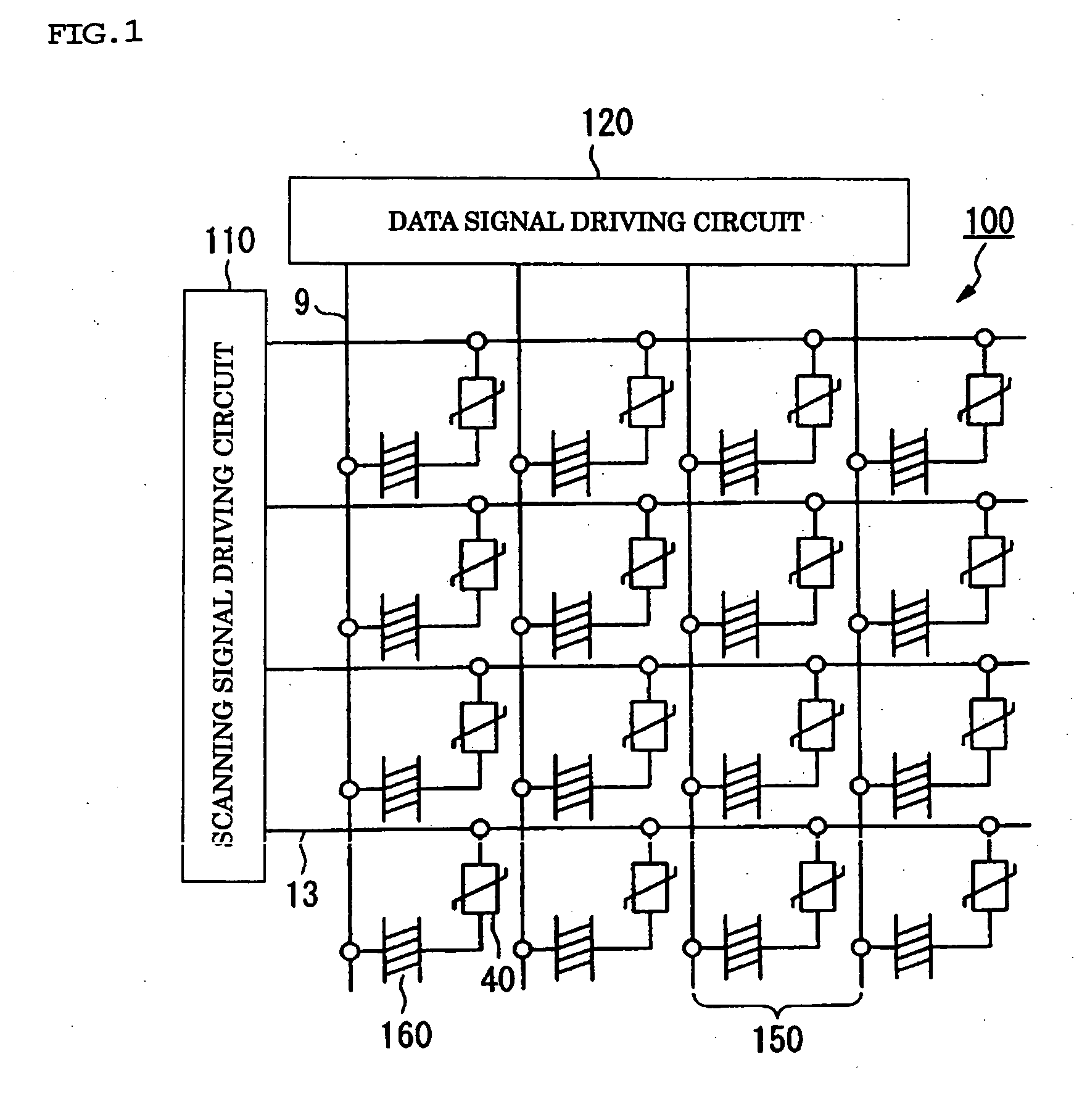
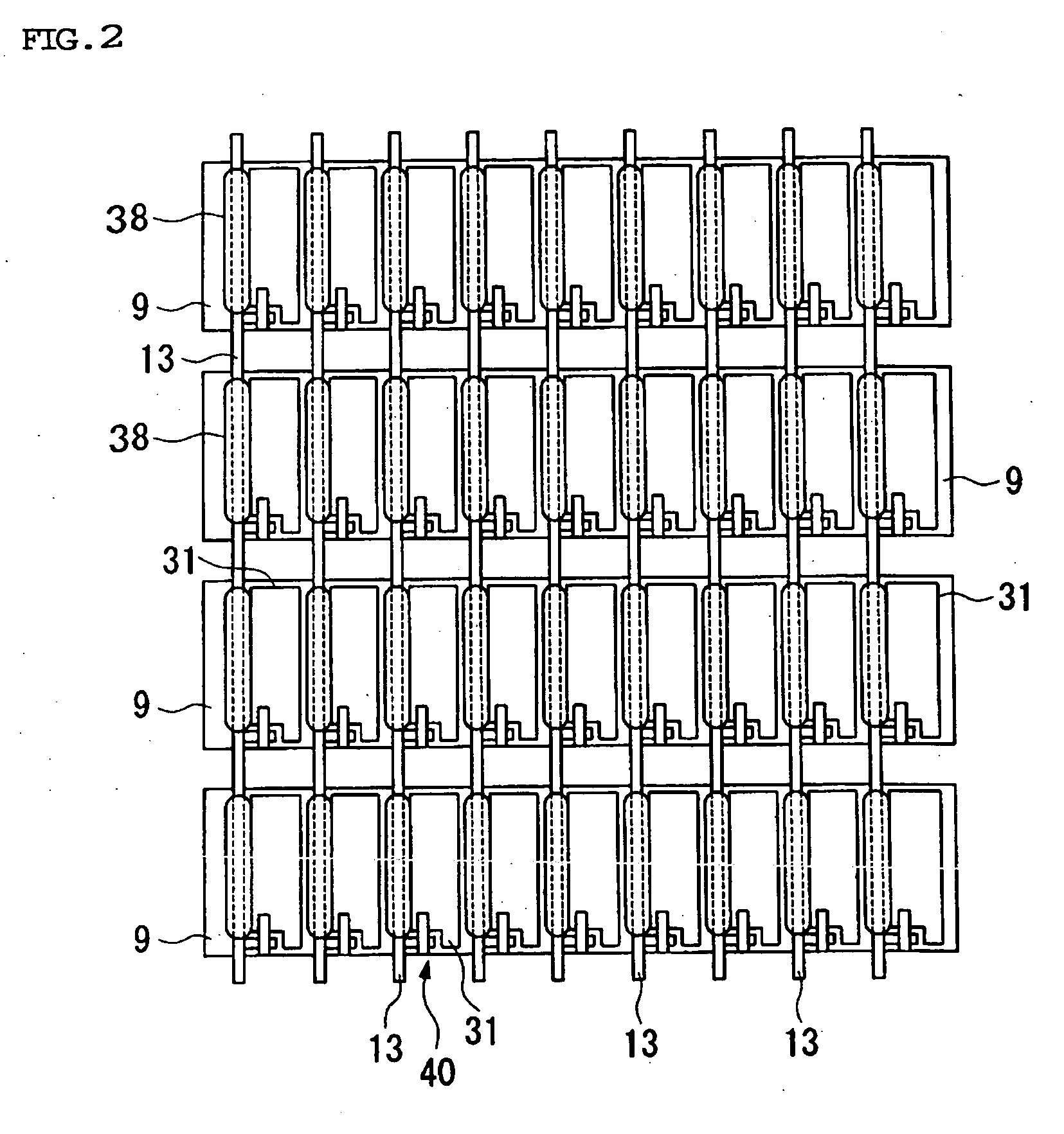
[0056]FIG. 1 is a schematic of a liquid crystal display device 100 according to the present embodiment. The liquid crystal display device 100 includes a scanning signal driving circuit 110 and a data signal driving circuit 120. The liquid crystal display devi...

second exemplary embodiment

[0074] Second Exemplary Embodiment

[0075] A second exemplary embodiment of the present invention will now be described with reference to the drawings.

[0076] FIGS. 4(a) and 4(b) are schematics illustrating a liquid crystal display device 200 according to the second exemplary embodiment, and correspond to FIGS. 3(a) and 3(b) of the first exemplary embodiment. The basic structure of the liquid crystal display device according to the second exemplary embodiment is the same as that of the first exemplary embodiment. But positions in which the dielectric projections and electrode slits to control the alignment of liquid crystal molecules are formed are different from that of the first exemplary embodiment. In FIGS. 4(a) and 4(b), the same components as those in FIGS. 3(a) and 3(b) have the same reference numerals, and a detailed description thereof will be omitted.

[0077] As shown in FIGS. 4(a) and 4(b), in the liquid crystal display device 200 according to the second exemplary embodiment...

third exemplary embodiment

[0085] Third Exemplary Embodiment

[0086] Hereinafter, a third exemplary embodiment of the present invention will be described with reference to the drawings.

[0087] FIGS. 5(a) and 5(b) are schematics illustrating a liquid crystal display device 300 according to the third exemplary embodiment, and correspond to FIGS. 3(a) and 3(b) of the first exemplary embodiment. The basic structure of the liquid crystal display device according to the third exemplary embodiment is the same as that of the first exemplary embodiment, but the structure of the projections formed on the scanning lines is mainly different from that of the first exemplary embodiment. In FIG. 5, the same components as those in FIG. 3 have the same reference numerals, and a detailed description thereof will be omitted.

[0088] As shown in FIG. 5(a), in the liquid crystal display device 300 according to the third exemplary embodiment, a plurality of projections 38 made of a dielectric material, such as acrylic resin, are form...


PUM


Abstract

To provide a transflective liquid crystal display device in a vertical alignment mode that is capable of displaying bright and high-contrast images in a wide viewing angle range, a liquid crystal layer is interposed between a pair of substrates opposite to each other, and display is performed in a predetermined pixel unit. The liquid crystal layer is composed of liquid crystal having a vertical alignment in an initial state, specifically, having negative dielectric anisotropy. Signal lines through which signals are supplied to the pixels, are formed on the inner surface of either of the pair of substrates. Convex portions made of a dielectric material are formed around and/or on the signal lines on the inner surface of either of the pair of substrates.

Description

BACKGROUND OF THE INVENTION [0001] 1. Field of Invention [0002] Exemplary aspects of the present invention relate to a liquid crystal display device and an electronic apparatus, and more particularly, to a liquid crystal display device that is capable of displaying high-contrast images in a wide viewing angle range using vertical alignment type liquid crystal molecules. [0003] 2. Description of Related Art [0004] A related art transflective liquid crystal display device having both a reflective display mode and a transmissive display mode can be used as a liquid crystal display device. A related art liquid crystal display device has been disclosed to include a transflective liquid crystal display device in which a liquid crystal layer is interposed between an upper substrate and a lower substrate. An inner surface of the lower substrate is provided with a reflective film composed of a metal film, such as aluminum film, having an opening for transmitting light therein. The reflective...

Claims


Application Information

Patent Timeline
IPC IPC(8): G02F1/1333G02F1/1335G02F1/1337G02F1/1343G02F1/139
CPCG02F1/1333G02F2001/133776G02F1/1393G02F1/134309G02F1/133776G02F1/1335
Inventor MAEDA, TSUYOSHIKURASAWA, HAYATONISHIMURA, JOJI
Owner SEIKO EPSON CORP
Why Eureka
Try Eureka