Mounting apparatus for storage devices

Inactive Publication Date: 2005-06-02
HONG FU JIN PRECISION IND (SHENZHEN) CO LTD +1
View PDF7 Cites 9 Cited by
  • Summary
  • Abstract
  • Description
  • Claims
  • Application Information

AI Technical Summary

Benefits of technology

[0008] Accordingly, an object of the present invention is to provide a reliabl

Problems solved by technology

The ear abuts against the fixing plate before said latch

Method used


Image

  • Mounting apparatus for storage devices
  • Mounting apparatus for storage devices
  • Mounting apparatus for storage devices

Examples


Embodiment Construction

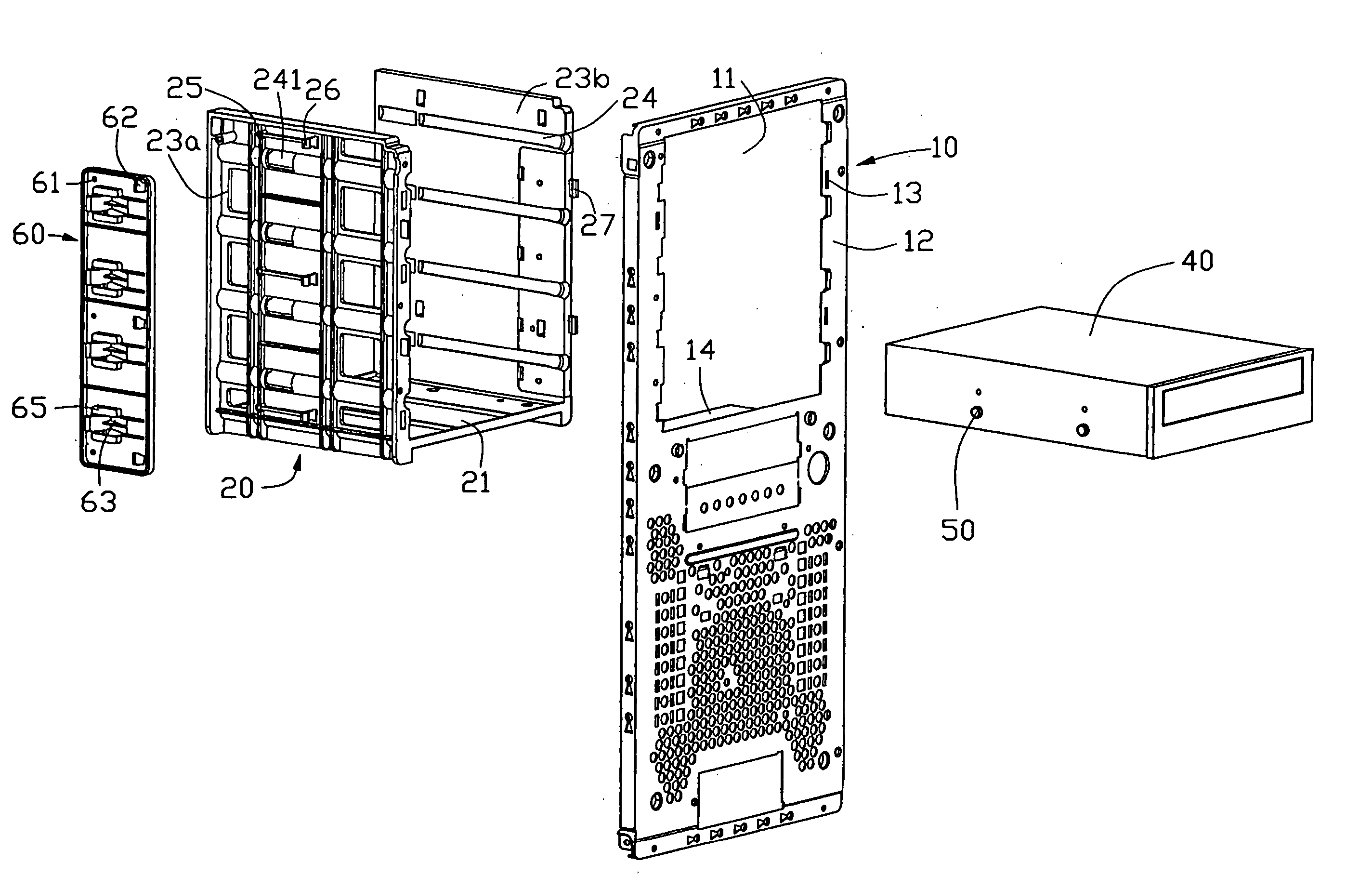
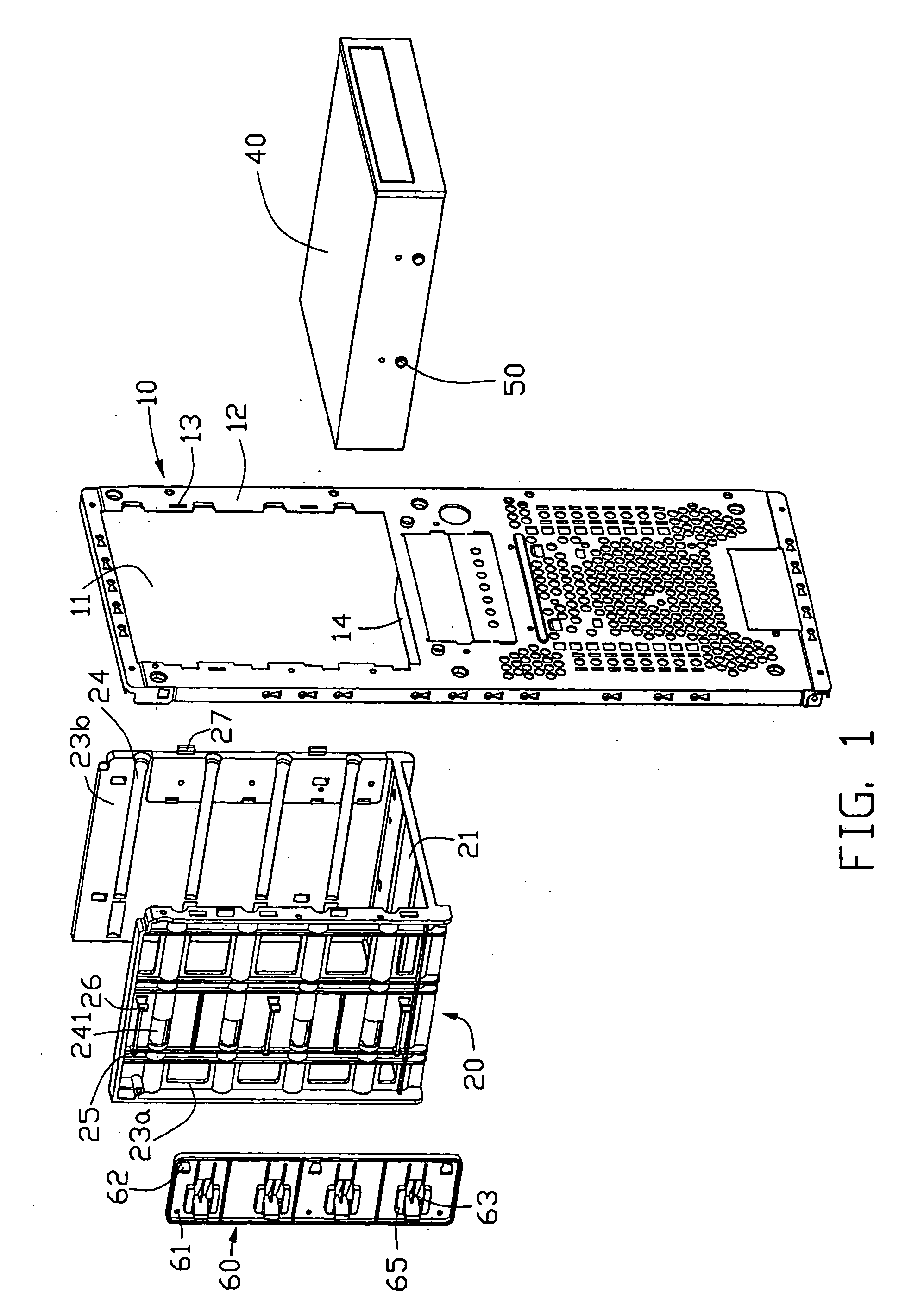
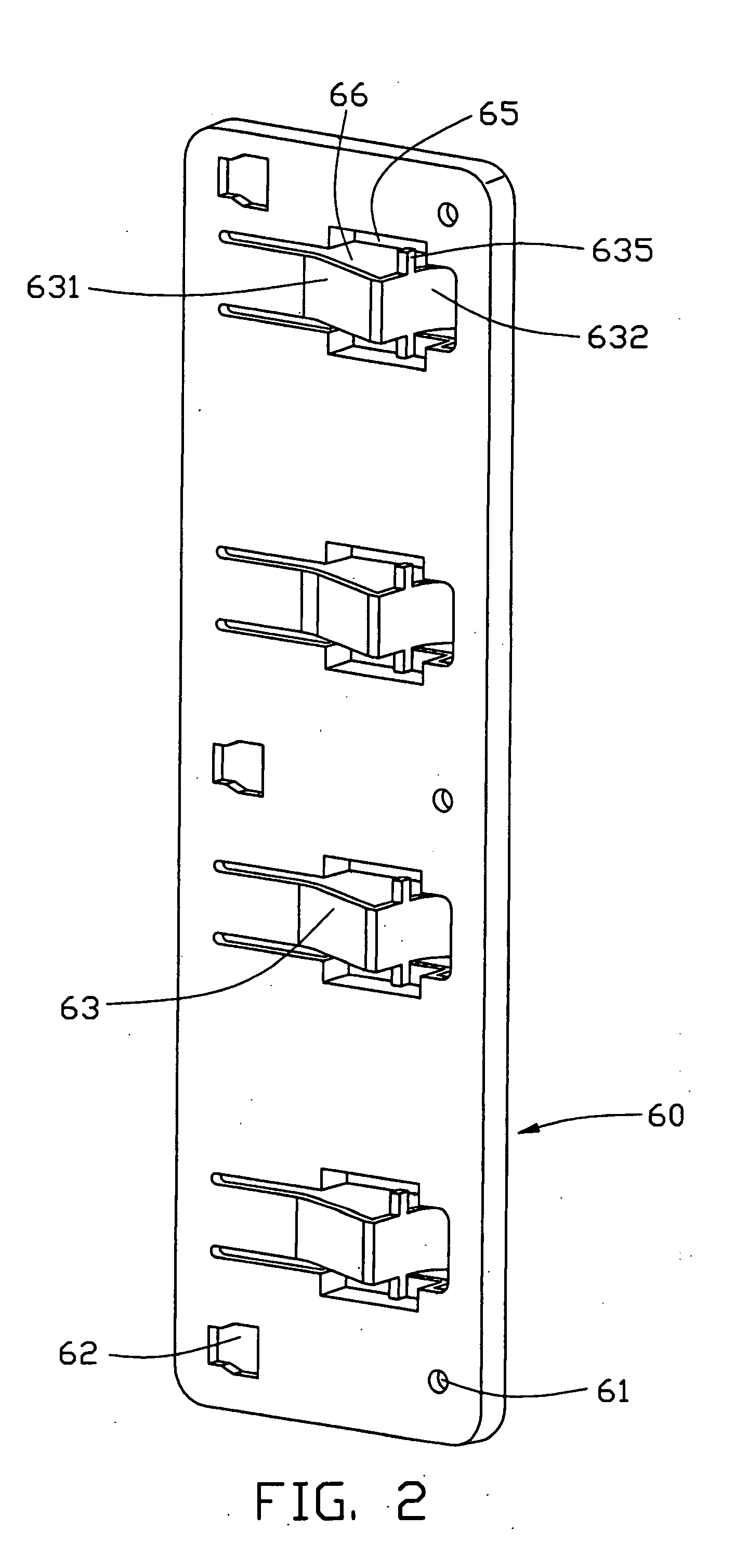
[0015] Referring to FIGS. 1 and 4, a mounting apparatus in accordance with the preferred embodiment of the present invention is provided for holding a storage device 40 in place. The storage device has a plurality of screws 50 attached to two sides thereof. The mounting apparatus comprises a fixing plate 60 and a storage bracket 20 attached to a front plate 10 of a computer enclosure.

[0016] The front plate 10 defines an opening 11 corresponding to the storage bracket 20, thereby the storage device being inserted through the opening 11 into the storage bracket 20. A plurality of slits 13 is defined at two sides 12 of the opening 11. A rack 14 is bent inward at the bottom edge of the opening 11 for supporting the storage bracket 10.

[0017] The U-shaped storage bracket 20 comprises a bottom panel 21 and a pair of side panels 23a, 23b. The side panels 23a, 23b have flanges. Corresponding to the slits 13 on the front plate 10, a plurality of barbs 27 is formed on the front flange of the...


PUM


Abstract

A mounting apparatus for a storage device (40) include a storage bracket (20) and a fixing plate (60). The storage bracket has a side panel (23a) defining at least one groove (24) for slidingly receiving the storage device. The fixing plate is attached to the side panel of the storage bracket. The fixing plate has at least one resilient latch (63) corresponding to the groove for securing the storage device. At least one ear (635) is formed on the latch. The ear abuts against the fixing plate before said latch is deformed excessively for releasing the storage device.

Description

BACKGROUND OF THE INVENTION [0001] 1. Field of the Invention [0002] The present invention relates to mounting apparatuses, and particularly to mounting apparatuses that readily attach data storage devices in brackets of a computer enclosure. [0003] 2. Description of the Related Art [0004] Various data storage devices are installed in computers for communication and handling of data. Such devices include, for example, hard disk drives, floppy disk drives, and CD-ROM drives. [0005] A conventional data storage device is directly attached to a computer enclosure with bolts. However, attachment with bolts is unduly complicated and time-consuming. [0006] In U.S. Pat. No. 6,373,694, a fastening device is disclosed to mount a data storage device to a computer enclosure. The fastening device is configured on a frame to have a plurality of pairs of opposed grooves, a block member on one side of the frame with grooves disposed thereon, and a plurality of latched members disposed on the block m...

Claims


Application Information

Patent Timeline
IPC IPC(8): G06F1/16G06F1/18H05K7/00H05K7/14
CPCG06F1/187G06F1/184
Inventor HAN, SHAO-BO
Owner HONG FU JIN PRECISION IND (SHENZHEN) CO LTD
Why Eureka
Try Eureka