Resistance voltage divider circuit, liquid crystal display driving apparatus using resistance voltage divider circuit, and liquid crystal display apparatus

a technology of resistance voltage and divider circuit, which is applied in the direction of transmission systems, physical parameters compensation/prevention, instruments, etc., can solve the problem of difficulty in generating a low resistance value equal or lower than the interface resistance, and achieve the effect of accurate gradation voltage and improved gradation display

Inactive Publication Date: 2005-06-30
PANASONIC CORP
View PDF11 Cites 15 Cited by
  • Summary
  • Abstract
  • Description
  • Claims
  • Application Information

AI Technical Summary

Benefits of technology

[0013] With this configuration, it is possible to apply an accurate gradation voltage (analog voltage) from the liquid crystal display driving apparatus to the drive

Problems solved by technology

However, in the presence of a large interface resistance component on an interface between a resistor near a contact and

Method used


Image

  • Resistance voltage divider circuit, liquid crystal display driving apparatus using resistance voltage divider circuit, and liquid crystal display apparatus
  • Resistance voltage divider circuit, liquid crystal display driving apparatus using resistance voltage divider circuit, and liquid crystal display apparatus
  • Resistance voltage divider circuit, liquid crystal display driving apparatus using resistance voltage divider circuit, and liquid crystal display apparatus

Examples


embodiment 1

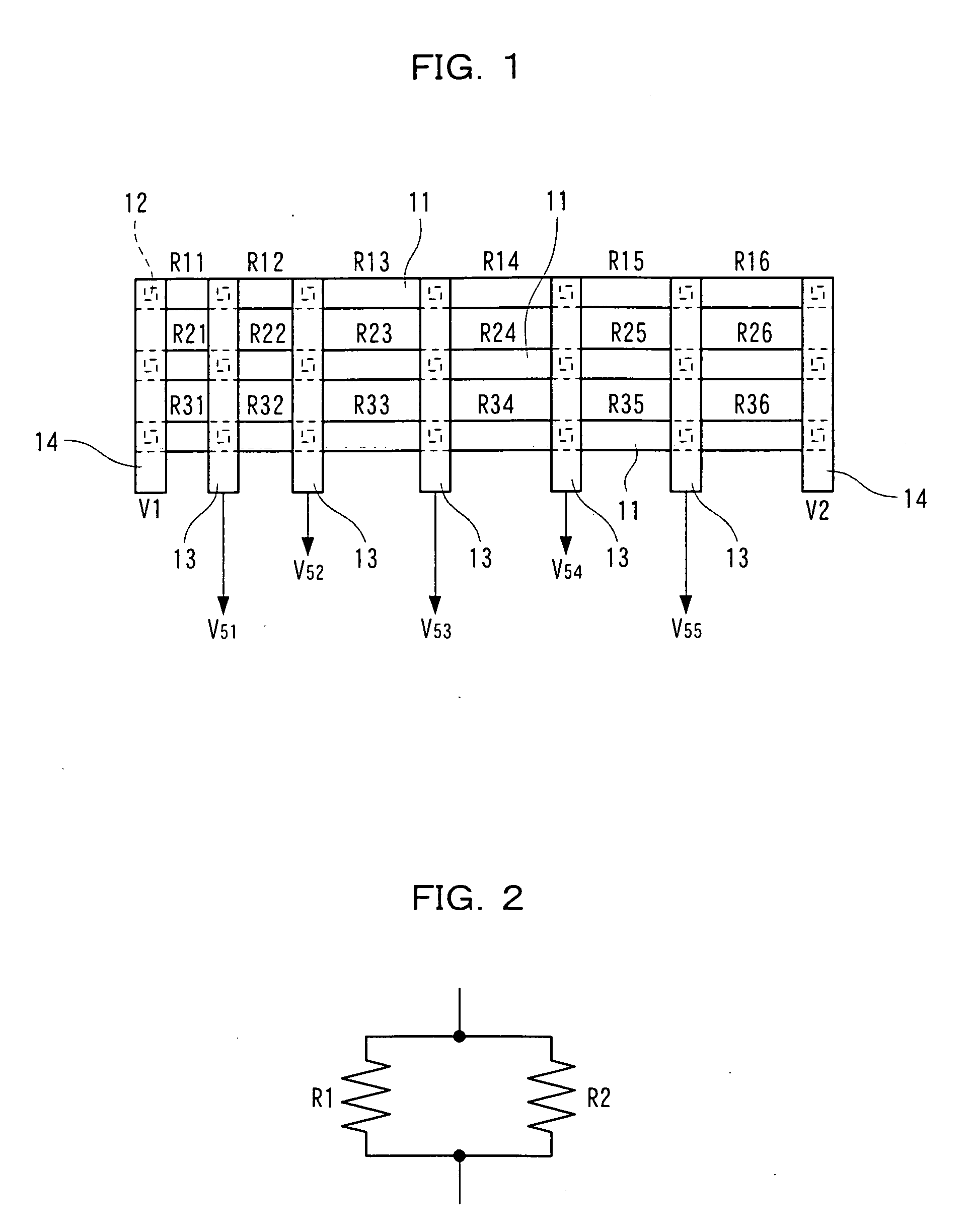
[0022]FIG. 1 is a structural diagram showing the resistance voltage divider circuit for a liquid crystal display driving apparatus (a resistance voltage divider circuit included in a gradation voltage generation circuit which generates a gradation voltage for driving a liquid crystal element) according to Embodiment 1 of the present invention.

[0023] As shown in FIG. 1, a plurality of (three in FIG. 1) resistors 11 are provided which are almost equal in resistance value and have a plurality of (seven in FIG. 1) contacts 12, on which gradation voltages are extracted, at the equal positions with respect to the horizontal direction of FIG. 1. Resistance values between the contacts 12 of the three resistors 11 have the relationship of R11:R12:R13: . . . :R16=R21:R22:R23: . . . :R26=R31:R32:R33: . . . :R36 where R11, R12, R13, . . . R16 represent resistance values between the contacts of a first resistor of the resistors 11, R21, R22, R23, . . . R26 represent resistance values between th...

embodiment 2

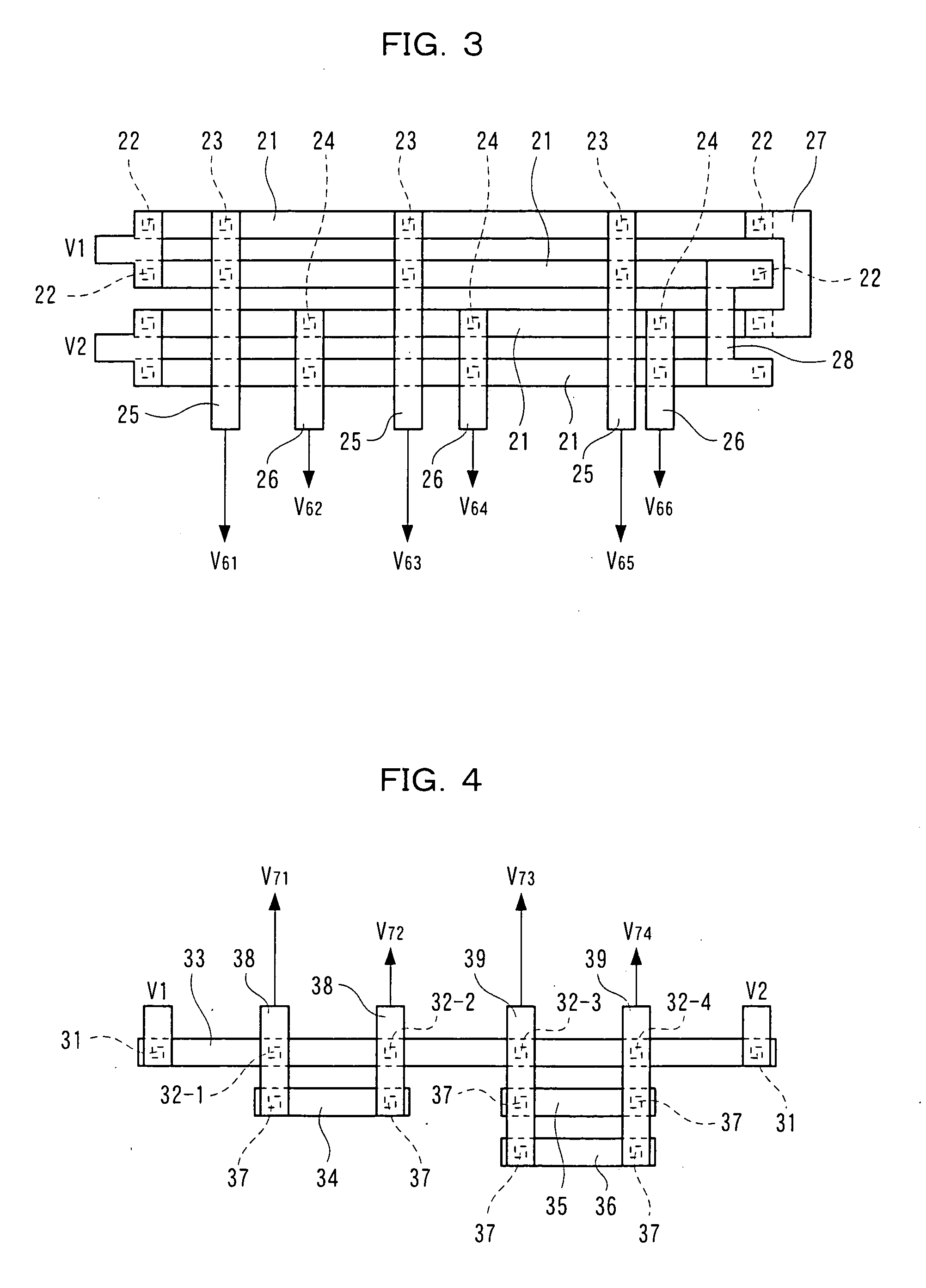
[0031]FIG. 3 is a structural diagram showing a resistance voltage divider circuit for a liquid crystal display driving apparatus according to Embodiment 2 of the present invention.

[0032] As shown in FIG. 3, 2N (N is an positive integer equal to or larger than 2) resistors 21 (four in FIG. 3) having almost equal resistance values are sequentially arranged in parallel with aligned longitudinal directions, and contacts 22 are provided on both ends of the resistors 21. Of the resistors 21 arranged in sequence, on the uppermost and second uppermost resistors 21 in FIG. 3, contacts 23 are provided at the equal positions with respect to the horizontal direction of FIG. 3. On the third and fourth uppermost resistors 21 in FIG. 3, contacts 24 are provided at the equal positions with respect to the horizontal direction of FIG. 3. The embodiment of FIG. 3 shows an example in which the positions of the contacts 24 are different from those of the contacts 23 with respect to the horizontal direc...

embodiment 3

[0039]FIG. 4 is a structural diagram showing a resistance voltage divider circuit for a liquid crystal display driving apparatus according to Embodiment 3 of the present invention.

[0040] As shown in FIG. 4, a first resistor 33 is provided which has contacts 31 on both ends and a plurality of (four in FIG. 4) contacts 32-1 to 32-4 between both ends. Further, only on portions requiring low resistances, second resistors are provided so as to face the contacts 32-1 to 32-4 of the first resistor 33. In FIG. 4, a second resistor 34 having contacts 37 on both ends is provided in parallel with the first resistor 33 so as to face the contacts 32-1 and 32-2 of the first resistor 33, and two second resistors 35 and 36, each of which has contacts 37 on both ends, are provided in parallel with the first resistor 33 so as to face the contacts 32-3 and 32-4 of the first resistor 33.

[0041] Further, the contacts 32-1 and 32-2 of the first resistor 33 and the contacts 37 on both ends of the second ...


PUM


Abstract

A resistance voltage divider circuit of a gradation potential generation circuit for adjustment, which generates a gradation potential for driving a liquid crystal device. The circuit includes three resistors (11) which are equal in resistance value and have contacts (12) at equal positions. The contacts (12) at the equal positions of each resistors (11) are connected to one another so as to connect the resistors in parallel, reference potentials V1 and V2 are inputted across the resistors connected in parallel, and a gradation potential is generated on a junction point of the contact (12) according to a voltage divided by the resistors (11).

Description

FIELD OF THE INVENTION [0001] The present invention relates to a resistance voltage divider circuit included in a gradation voltage generation circuit. BACKGROUND OF THE INVENTION [0002] A gradation voltage generation circuit generates a gradation voltage for driving a display device such as a liquid crystal element. For example, when a liquid crystal element is driven in a liquid crystal display apparatus, two or more reference voltages are first inputted to the gradation voltage generation circuit. The gradation voltage generation circuit minutely divides a voltage between the reference voltages so as to generate gradation voltages (or gradation voltages for γ correction) necessary for driving the liquid crystal element. [0003] Further, more gradation voltages are necessary because display panels such as recent liquid crystal panels display more colors with higher definition. Thus, a voltage difference has decreased between adjacent gradations. This means that a gradation voltage ...

Claims


Application Information

Patent Timeline
IPC IPC(8): G09G3/20G09G3/36G02F1/133H03M1/06H03M1/76
CPCG09G3/3688H03M1/765H03M1/0678G09G2320/0276
Inventor NISHI, KAZUYOSHIMURATA, MASAHIDE
Owner PANASONIC CORP
Why Eureka
Try Eureka