Drift tire and remote control car having tire attached thereto

a technology of remote control and tire, which is applied in the direction of remote control toys, non-skid devices, transportation and packaging, etc., can solve the problems of inability to achieve drift run intended by manipulators, difficult pipe attachment, and inability to achieve drift run, etc., to achieve convenient attachment and replacement of drift tires, reduce traction, and enjoy the effect of tires

Active Publication Date: 2005-07-07
YOKOMO
View PDF13 Cites 6 Cited by
  • Summary
  • Abstract
  • Description
  • Claims
  • Application Information

AI Technical Summary

Benefits of technology

[0019] In accordance with at least one embodiment of the present invention, the drift tire can maintain traction with a road surface by the ring and the annular body with respect to the run in the circumferential direction of the tire, even in the case of fitting the ring to the annular groove on the outer surface of the annular body. Further, in the case of steering the tire toward a lateral direction, traction with a road surface is generated mainly by the ring, so that traction can significantly be reduced, whereby it is possible to generate a side slip phenomenon. Accordingly, as well as the normal linear run, it is possible to enjoy the drift run at a corner and the drift run in a narrow space and various places.
[0020] Further, in at least one embodiment of the present invention, it is possible to appropriately select an extent of difficulty in changing to the drift run by appropriately selecting the number and the kind of the rings fitted to the outer surface of the tire and the kind of the annular body. Accordingly, when a user recognizes the state of a road surface, the user can freely select the number and the kinds of rings. Thus, it is possible to obtain different results in accordance with the quality of the selection, and the user can better enjoy use of the tires.
[0021] Further, in accordance with at least one embodiment of the present invention, the drift tire can be attached to front wheels and rear wheels of a remote control car and the like, or only to the rear wheels, it is possible to easily attach and replace the drift tires, and it is possible to change the drift state of the vehicle.

Problems solved by technology

There is no technical development undertaken for a tire expected to perform a drift run.
In order to achieve the drift run, a manipulator controls and changes an angle of the tire in a slipping direction; however, since the tire itself is structured so as to achieve the grip run as mentioned above, and a frictional force with respect to the road surface is applied, the drift run intended by the manipulator can not be achieved, and in some cases, a vehicle has a fall.
However, in the case of the pipe, it is hard to attach the pipe, and in the case of the tapes, the tapes frequently drop out more easily than the tire.
Further, in order to make the running road surface itself slippery, the road surface is designed to be formed by a P-tile or be coated with a wax; however, there is a problem in that the road surface must be specifically constituted.

Method used


Image

  • Drift tire and remote control car having tire attached thereto
  • Drift tire and remote control car having tire attached thereto
  • Drift tire and remote control car having tire attached thereto

Examples


embodiment 1

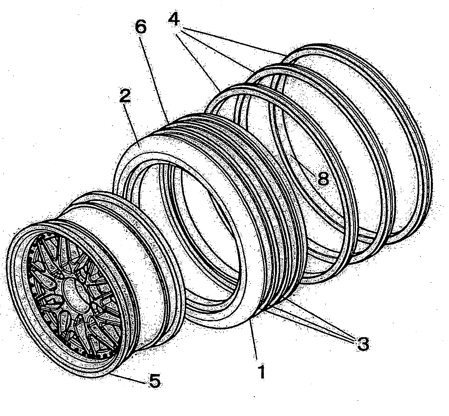
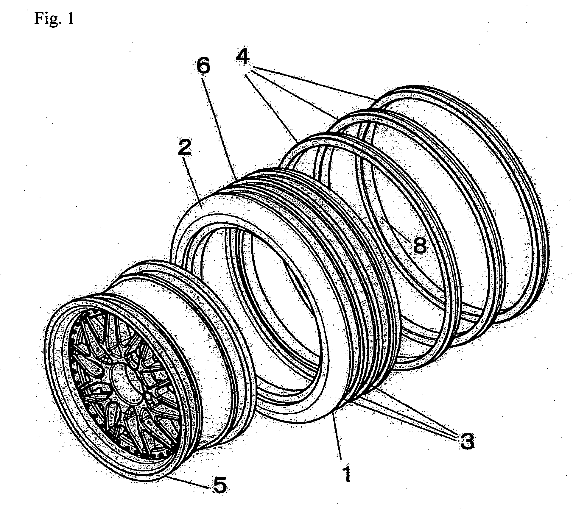
[0040]FIG. 1 is a perspective view in which a drift tire in accordance an embodiment of with the present invention is exploded, FIG. 2 is a perspective view of an assembly thereof, and FIG. 3 is a partly cross sectional side elevational view of the drift tire.

[0041] Reference numeral 1 denotes a tire main body, reference numeral 2 denotes an annular body forming an outer peripheral surface of the tire main body 1, reference numeral 3 denotes an annular groove formed on an outer surface of the annular body 2, reference numeral 4 denotes a ring to be fitted to the annular groove 3, and reference numeral 5 denotes a wheel.

[0042] The annular body 2 is a tubular body made of a rubber based material which is normally used as a material for the tire, and is constituted by an annular outer peripheral body 6, flanges 7 folded to an inner side from both side edge portions of the outer peripheral body 6, and annular grooves 3 formed on an outer surface of the outer peripheral surface 6 in a ...

embodiment 2

[0049] An embodiment 2 in accordance with an embodiment of the present invention is structured such that the annular body is formed as a tubular body made of a synthetic resin based material, and a suitable number of annular grooves are formed in a circumferential direction of the surface of the annular body. Rings each being made of a rubber based material are fitted to the annular grooves in a closely attached state.

[0050] The ring can be easily fitted to the annular groove by expanding the elastic ring to enlarge its loop.

embodiment 3

[0051]FIG. 4 is a perspective view showing an exploded state of the drift tire in accordance with an embodiment of the present invention in the same manner as the embodiments 1 and 2 mentioned above, FIG. 5 is a perspective view of an assembly thereof, and FIG. 6 is a partly cross sectional side elevational view of the same.

[0052] The tire main body 11 is made of a synthetic resin based material in the same manner as the embodiment 2 mentioned above, and is constituted by an annular body 12 forming an outer peripheral surface, an inner folded portion 13 of an edge portion of the annular body 12, an inner reinforcing member 14 connected to the inner folded portion 13, a disc 15 in a front surface side of the inner reinforcing member 14, annular grooves 16 formed in a circumferential direction of an outer surface of the annular body 12, and rubber based rings 17 fitted to the annular grooves 16 in a closely attached state.

[0053] The annular body 12 forms the inner folded portion 13 ...


PUM


Abstract

Both a “grip” run and a drift run of a remote control car are achieved by fitting rings to an outer peripheral surface of a tire or tires. In a drift tire, at least one annular groove is formed on an outer surface of an annular body of a tire main body in a circumferential direction, at least one ring made of a different material and/or shape from that of the annular body is fitted to the annular groove, and the ring is level with or protrudes from the outer surface of the annular body.

Description

BACKGROUND OF THE INVENTION [0001] 1. Field of the Invention [0002] The present invention relates generally to a remote control car represented by a radio control car, and more particularly to a drift tire by which a drift run can be easily achieved, and a remote control car to which the tire is attached. [0003] 2. Description of the Related Art [0004] In general, the run of a remote control car is mainly constituted by a “grip” run, and a main object of the remote control car is to stably run and compete in speed. Accordingly, in the tire used in the remote control car, in order to improve traction (a grip force) with various road surfaces, concavity and convexity having various shapes are formed on an outer surface of the tire, or a material likely to grip is selected (for example, Japanese Patent Laid-open No. 7-39652). [0005] As mentioned above, the tire in the conventional remote control car is provided for achieving the grip run, and a technical development has been focused on...

Claims


Application Information

Patent Timeline
Patent Type & Authority Applications(United States)
IPC IPC(8): A63H17/26A63H17/39B60C11/00B60C11/02B60C11/18
CPCA63H17/262B60C11/18B60C11/02
Inventor YOKOBORI, TOMOAKI
Owner YOKOMO
Why Eureka
Try Eureka