Brake rotor puller

a brake rotor and puller technology, applied in the field of pullers, can solve the problems of difficult removal of the rotor, needing replacement, and wear of the rotor with prolonged use, and achieve the effect of convenient removal of the brake rotor

Inactive Publication Date: 2005-08-18
PRO CUT INT
View PDF14 Cites 17 Cited by
  • Summary
  • Abstract
  • Description
  • Claims
  • Application Information

AI Technical Summary

Benefits of technology

[0007] The rotor puller of the present invention facilitates removing a brake rotor from a wheel hub of a vehicle onto which the brake rotor is mounted. The rotor puller has a pair of arm members with claws for engaging the brake rotor and a jack with an extendible piston for engaging the wheel hub.
[0010] The jack is pivotably connected to the arm members so as to pivot with respect thereto about the pivot axis. Thus, when the claws of the arm members are engaged with the brake rotor, the jack can be pivoted to align it with the wheel hub. Preferably, a pivot handle is connected to the jack to facilitate adjusting its inclination with respect to the arm members.
[0011] Preferably, each of the arm members has an arm handle for grasping by the user to facilitate moving the arm members against the bias of the spring means. The arm handles preferably extend substantially parallel to the pivot axis, and are set back somewhat from the claws to facilitate placing the claws over the brake rotor when clearance about the brake rotor is limited. An arm stop is preferably mounted to one of the arm members and configured to engage the other so as to limit the minimum separation between the arm members.
[0013] While the force of the spring means is typically sufficient to hold the claws in place on the rotor, for more positive retention it is preferred for one of the claws to have a pin passage therethrough that is spaced apart from the claw surface a sufficient distance to accommodate the thickness of the brake rotor. A retainer pin can be inserted into the pin passage to trap the brake rotor between the retainer pin and the claw surface to help maintain the claws in position on the brake rotor while the jack is operated.
[0015] To prevent damage to the wheel hub, it is preferred to mount a hub adapter onto the piston that is configured for engaging the specific style of wheel hub. The piston can be provided with an adapter mount that allows various hub adapters to be mounted to match the vehicle from which the rotor is being removed.

Problems solved by technology

These rotors become worn with prolonged use and periodically need to be replaced.
When the rotor has become so worn as to require replacement, it is frequently found to be affixed to the wheel hub by dirt and corrosion, making removal of the rotor difficult.
These devices require considerable care and effort in correctly placing the arm members to engage the shaft-mounted object as the extendible member is extended.
Correct placement of the arm members is further complicated in the case of vehicle brake rotors, since these rotors typically are recessed in a wheel well of the vehicle and there is typically surrounding structure, such as brake calipers, that severely limits access to the rotor.
However, in both devices the adjustment mechanism is bulky and would not appear to be suitable for use where clearances are limited, such as for use removing vehicle brake rotors.

Method used


Image

  • Brake rotor puller
  • Brake rotor puller
  • Brake rotor puller

Examples


Embodiment Construction

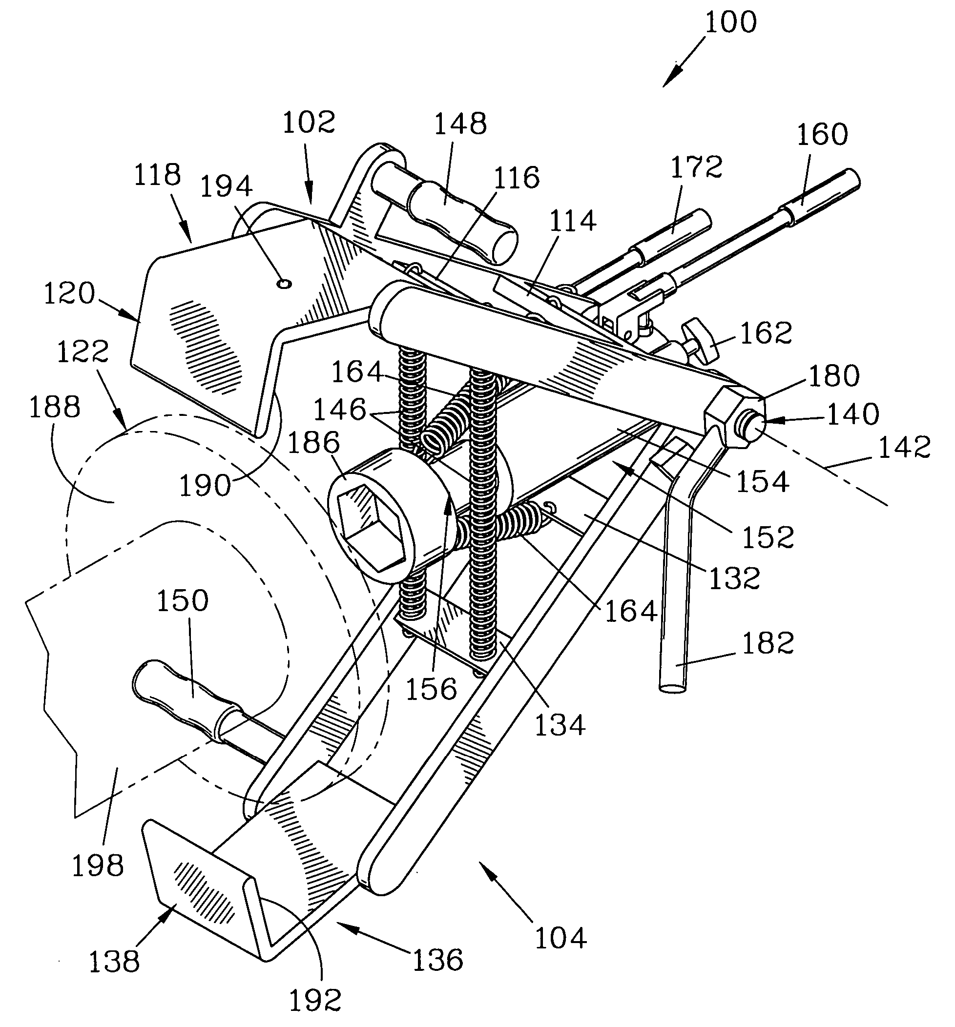
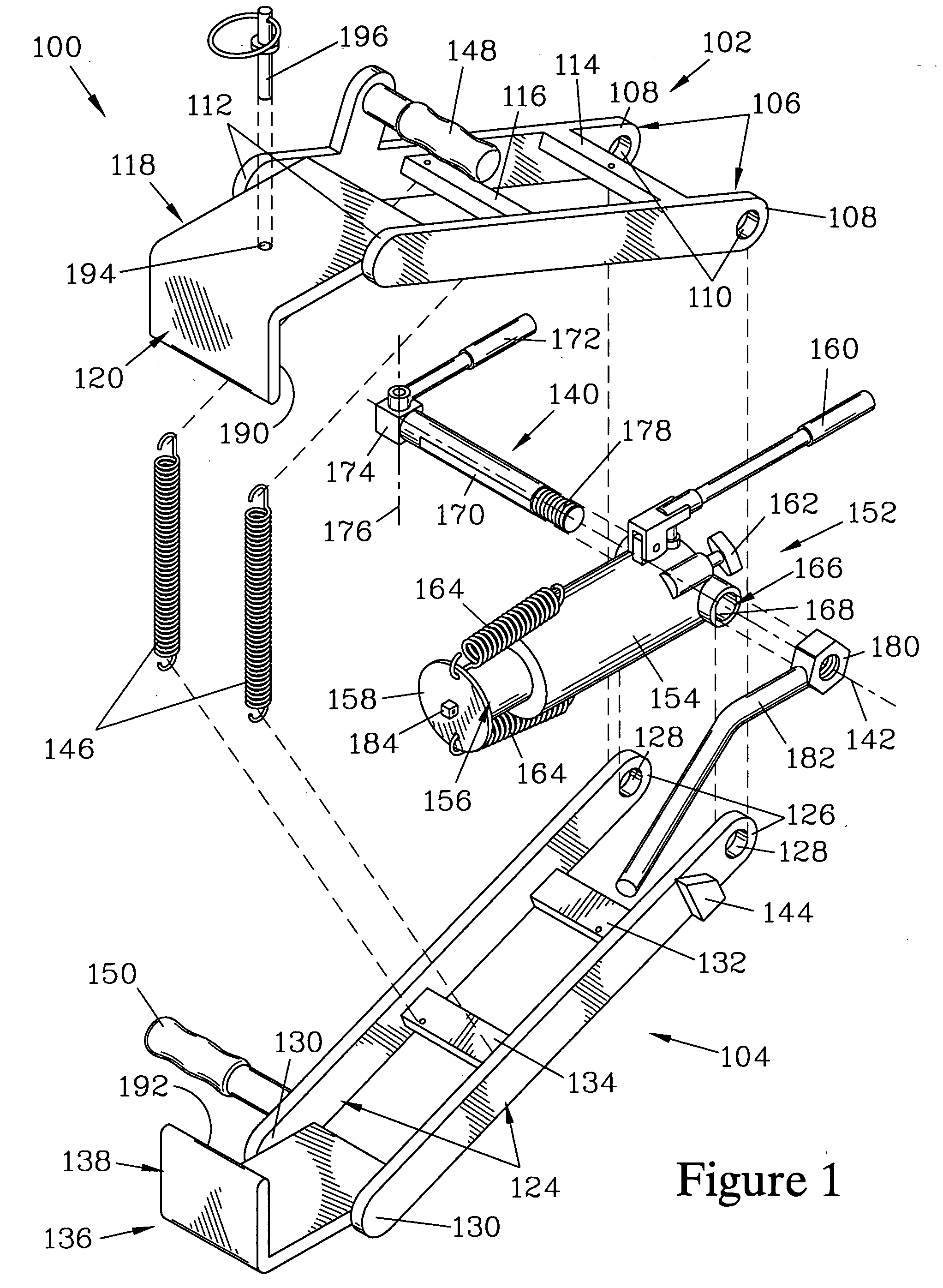
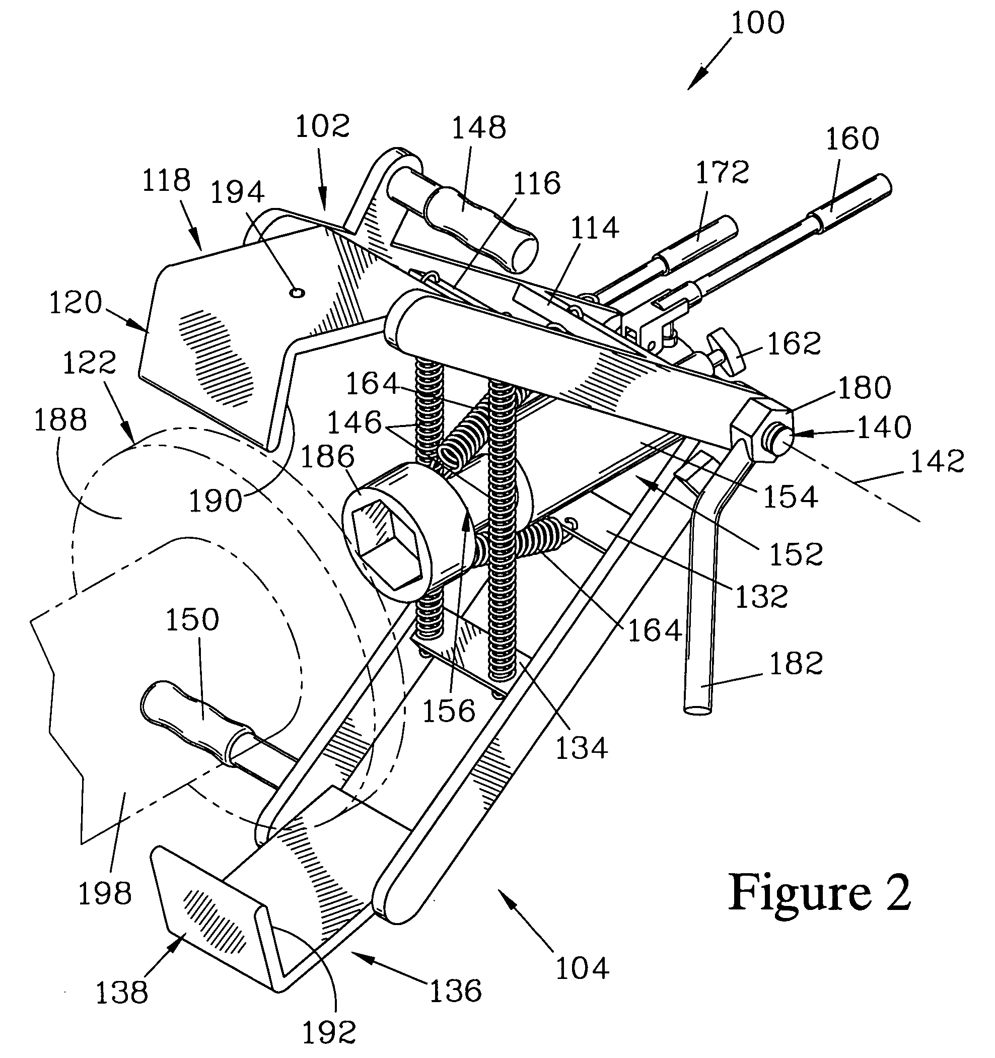
[0024]FIG. 1 is an exploded isometric view of a rotor puller 100 that forms one embodiment of the present invention. The rotor puller 100 is shown assembled in FIGS. 2-6.

[0025] The rotor puller 100 has a first arm member 102 and a second arm member 104 that are pivotably connected together when the rotor puller 100 is assembled. The first arm member 102 is formed by a pair of parallel first arm bars 106, each terminating at a first arm bar base end 108, having a first arm pivot passage 110 therethrough, and a first arm bar work end 112. The first arm bars 106 are joined together by a first arm member base crossbar 114, a first arm member mid crossbar 116, and a first claw plate 118 that joins the first arm bars 106 together at their first arm bar work ends 112. The first claw plate 118 is configured to provide a first claw 120 that is positioned to forcibly engage a brake rotor 122 (shown in FIGS. 3-5 and shown in phantom in FIGS. 2 and 6.)

[0026] The second arm member 104 is simil...


PUM

PropertyMeasurementUnit
angleaaaaaaaaaa
braking forceaaaaaaaaaa
corrosionaaaaaaaaaa

Abstract

A rotor puller has two arm members, ending at claws, and a jack with an extendible piston. The arm members and the jack are pivotably attached together about a pivot axis. Springs bias the arm members toward each other. The claws are placed over a brake rotor and retained thereon by a pin. After the claws have been placed, the jack is centered and activated to extend the piston towards the claws. The piston forcibly engages a wheel hub while the claws forcibly engage the rotor, pulling it from the wheel hub. Handles on the arm members facilitate placement of the claws over the rotor.

Description

FIELD OF THE INVENTION [0001] The present invention is a puller for removing an object from a shaft on which it is mounted, and more particularly for a puller that is well suited for use removing a vehicle brake rotor from a wheel hub. BACKGROUND OF THE INVENTION [0002] Vehicle disk brakes employ a rotor surrounding each wheel hub as a friction surface that is engaged by calipers to apply a braking force to a wheel mounted on the wheel hub. These rotors become worn with prolonged use and periodically need to be replaced. When the rotor has become so worn as to require replacement, it is frequently found to be affixed to the wheel hub by dirt and corrosion, making removal of the rotor difficult. A device for mechanically forcing the rotor from the hub is desirable to facilitate removal. [0003] A classic device for removing an object from a shaft is known as a gear puller, which employs two or more arm members that engage a shaft-mounted gear, and an extendible member that engages the...

Claims


Application Information

Patent Timeline
Patent Type & Authority Applications(United States)
IPC IPC(8): B25B27/02B25B27/06
CPCB25B27/026Y10T29/5383B25B27/064
Inventor WILLIAMS, WILLIAM A.
Owner PRO CUT INT
Why Eureka
Try Eureka