High frequency heating apparatus

a heating apparatus and high frequency technology, applied in the field of high frequency heating apparatus, can solve the problems of cumbersome preparation of tools, dirt can be hardly removed, and the air-exhausting grille b>8/b> cannot be dismounted, so as to reduce the sound of wind cutting and wind resistance in the air-exhausting path, improve the cleaning work of the air-exhausting grille, and improve the effect of cleaning appliances

Inactive Publication Date: 2005-08-18
PANASONIC CORP
View PDF16 Cites 7 Cited by
  • Summary
  • Abstract
  • Description
  • Claims
  • Application Information

AI Technical Summary

Benefits of technology

[0012] The present invention has been made to solve the above-described conventional problems, and therefore, has an object to avoid a high frequency heating apparatus capable of simply mounting and / or dismounting an air-exhausting grille mounted on an upper portion of a main body without any tool to improve a detachability of the air-exhausting grille, capable of detaching the air-exhausting grille in safety and simple manners, and also capable of cleaning the air-exhausting grille in an easy manner, which may solve problems as to cumbersome tool-seeking works and dismounting of the air-exhausting grille by setting a stand. To solve the above-described problems, such a construction is employed. That is to say, screwing of an air-exhausting grille to a main body of a high frequency heating apparatus is avoided; a fixing claw portion is provided at an upper portion on the side of the air-exhausting grille; this fixing claw portion is inserted into a slit hole of the main body; and also, a fixing hooking portion provided a lower portion on the side of the air-exhausting grille is hooked to a hooking flange of the main body. Also, magneto joint plates are mounted in the vicinity of both side surfaces of the air-exhausting grille; and magneto fixing plates containing magnetos are arranged at a place located opposite to the magneto joint plates, so that the air-exhausting grille is fixed / mounted.
[0013] In accordance with the above-described high frequency heating apparatus of the present invention, a plurality of fixing claw portions having plurality of bent Z-shaped flanges are formed on an upper surface guide of said air-exhausting grille, and a plurality of fixing hooking portions having a plurality of notch portions are formed on a lower surface guide. Furthermore, a means for mounting the air-exhausting grille is arranged by utilizing these fixing claw portion and fixing hooking portion and by a slit hole and a hooking flange, which are provided on the main body. Also, another means for fixing the air-exhausting grille in a close contact manner is arranged by magneto joint plates and magneto fixing plates provided within both side surface guides. The use of fixing screws is avoided, the air-exhausting grille can be simply and easily mounted / dismounted without using any tool. As a result, the air-exhausting grille can be easily cleaned, and the clean high frequency heating apparatus can be obtained. Moreover, the present invention has also another object to provide a hanging type microwave oven constructed in such a manner that an integral type body having a U-shape and having no joint and no screw-fastening is constituted under the hanging type microwave oven; when a ventilating operation is performed by using a ventilation-purpose fan, a ventilating capability can be improved in low noise, and also, the hanging type microwave oven can be easily cleaned and can be made in a smart design, resulting in a good outer view thereof. Also, components under malfunction states can be readily replaced by normal components.
[0014] To solve the above-described problems, a high frequency heating apparatus, according to the present invention, is featured by that while a flat upper lid is arranged at an upper portion of a hanging type microwave oven, a body formed in a U-shape is mounted on both edge planes thereof, so that a replacement of a component can be easily carried out, and also, when the hanging type microwave oven is installed above a cooking instrument, a lower portion of this microwave oven has no joint portion.

Problems solved by technology

Also, since these mounting screws are located at higher portions, the air-exhausting grille 8 cannot be dismounted unless a stand is employed.
Thus, there are such problems that cumbersome works of preparing the tool are necessarily required, and also a care should be taken as to safety aspects such as injuries.
Thus, dirt can be hardly removed, which deteriorates the cleaning characteristic.
Also, since the joint and the screws are observed, in the case of the hanging type microwave oven, the body of this microwave oven under installation condition is located at eye-levels of users, so that this microwave oven owns a very poor design.
Also, when a component is brought into a malfunction condition and this malfunction component is replaced by a normal component, if the body is not completely removed from the microwave oven, then this malfunction component cannot be replaced.
Therefore, there is a problem that many steps of replacement operations are required.

Method used


Image

  • High frequency heating apparatus
  • High frequency heating apparatus
  • High frequency heating apparatus

Examples


embodiment 1

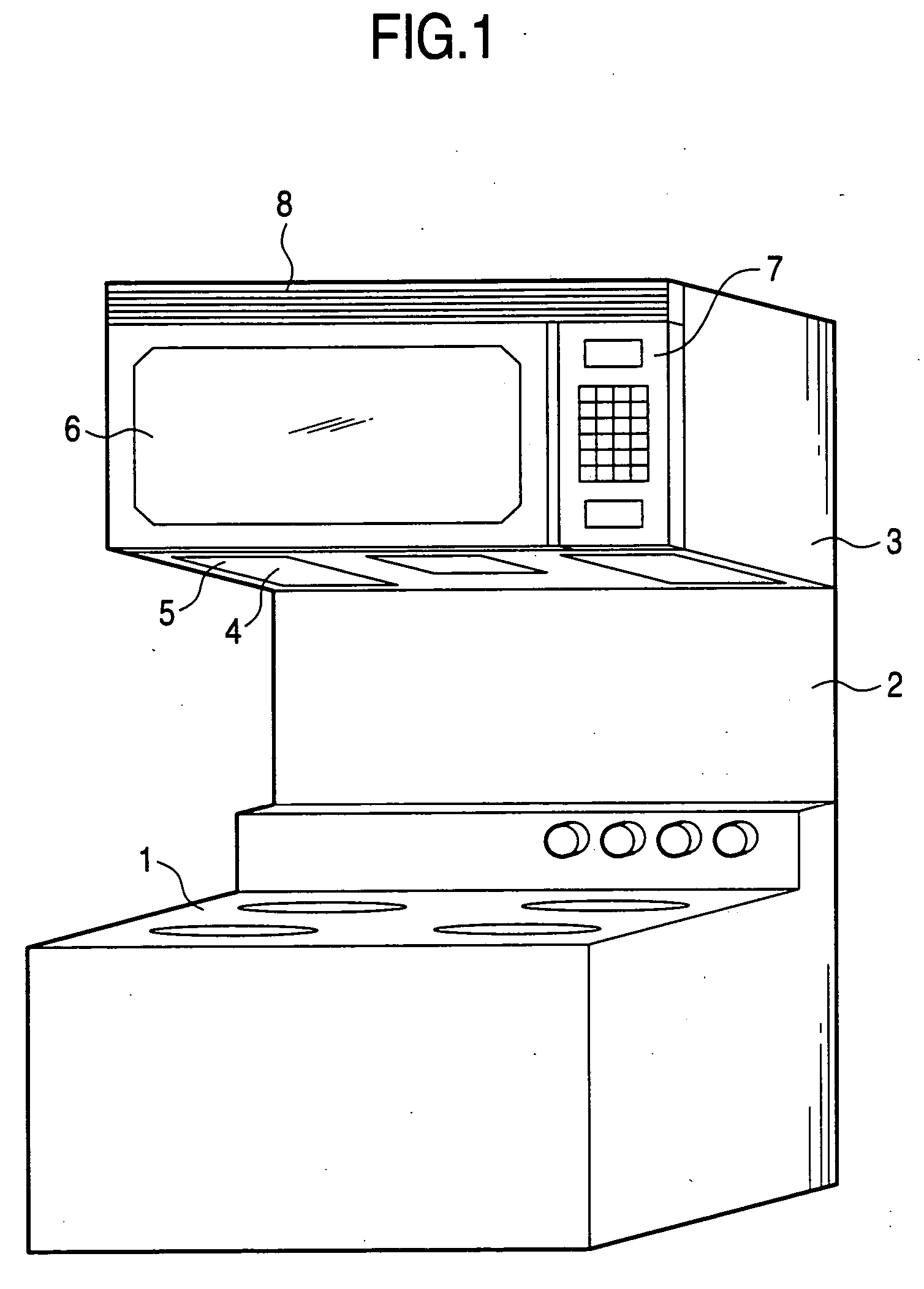
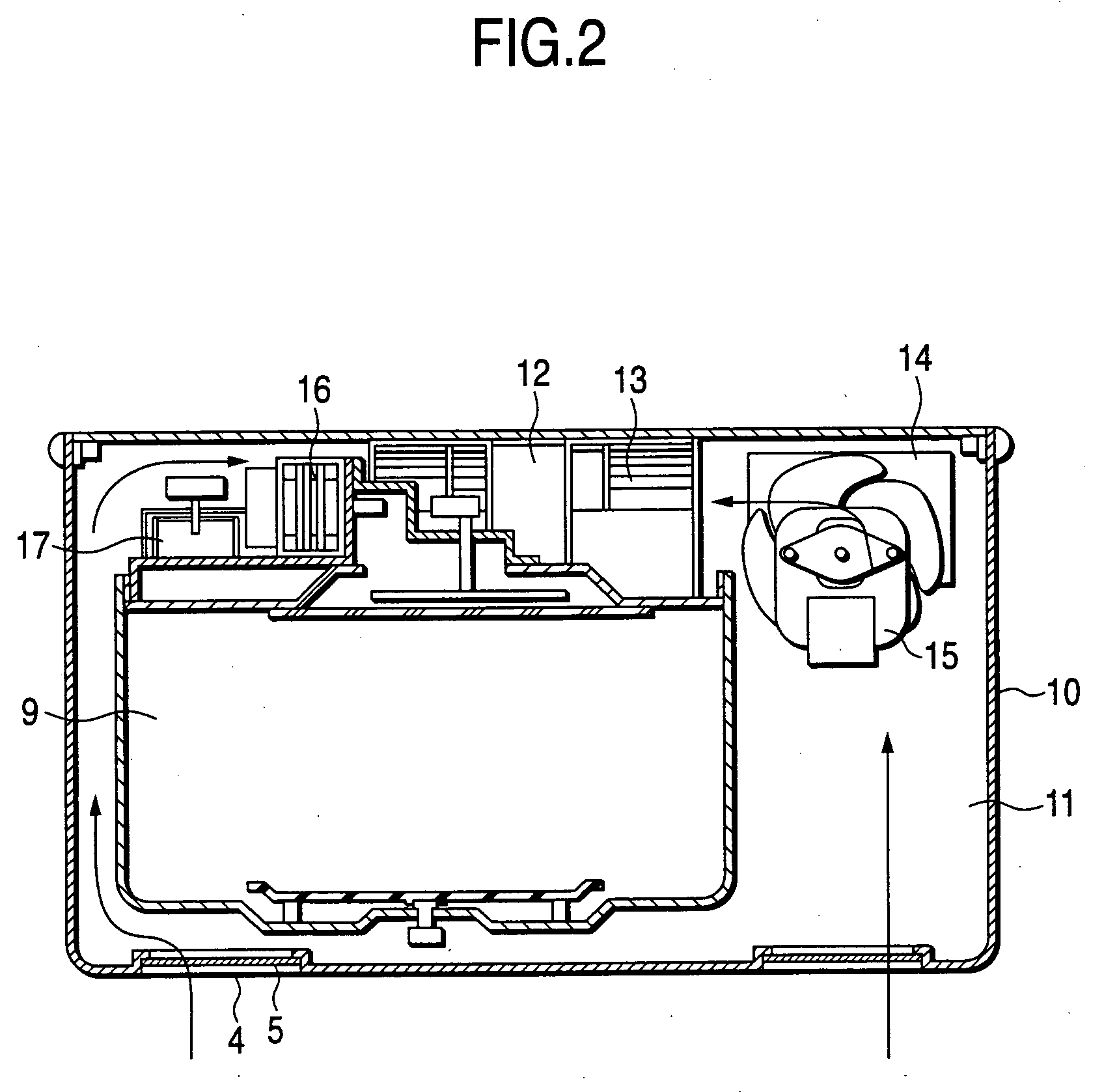
[0035]FIG. 1 is a diagram for representing a hanging type setting structure of a high frequency heating apparatus according to a first embodiment and a second embodiment of the present invention, and also shows the structure of the related art. FIG. 2 is a front sectional view for showing a main body of the high frequency heating apparatus according to the embodiment of the present invention. FIG. 3 is a diagram for partially indicating in detail an air-exhausting grille unit of this high frequency heating apparatus. FIG. 4 is a side sectional view for showing the grille unit of FIG. 3. FIG. 5 is a diagram for representing a mounting condition of the air-exhausting grille unit. FIG. 6 is a side sectional view for showing the conventional air-exhausting grille unit.

[0036] In FIG. 1, reference numeral 1 shows a cooking table on which several sets of either gas burners or electric burners are arranged, and a high frequency heating apparatus 3 is installed via a cooking space 2 at an u...

embodiment 2

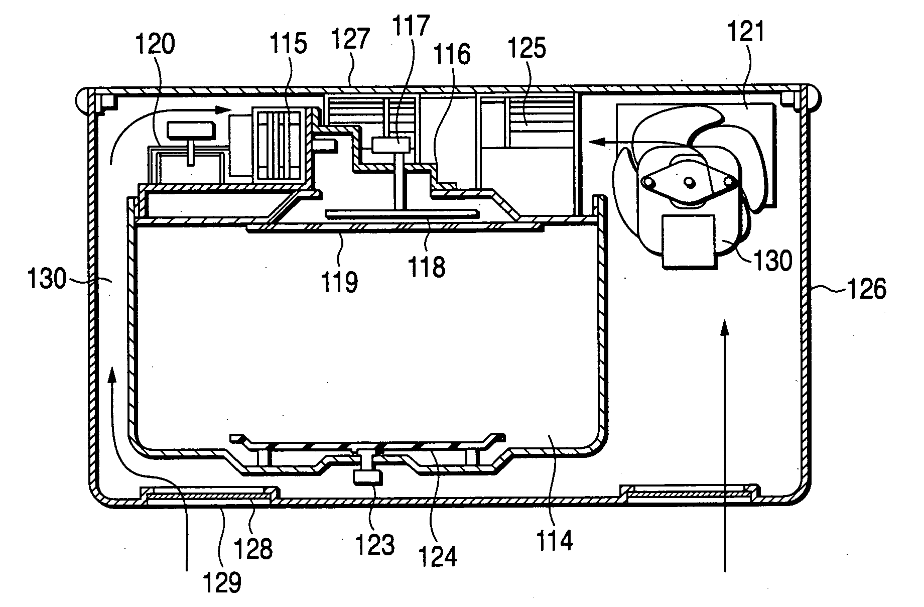
[0046]FIG. 7 shows a structural diagram of both a U-shaped body and an upper lid, which constitute a housing of a hanging type microwave oven according to an embodiment 2 of the present invention. FIG. 8 represents a setting condition diagram in the embodiment 2 of the present invention.

[0047] In FIG. 7, a heating chamber 114 is arranged in such a manner that a magnetron 115 for oscillating electromagnetic waves upwardly is connected to a waveguide 116 arranged on an upper surface of the heating chamber 114, a rotary antenna 118 is directed via a rotary motor 117 to an output port side of this waveguide 116, and a top plate 119 made of resin and mica is used to cover this heating chamber 114. A cooling-purpose scirocco fan motor 120 is provided behind the magnetron 115. Reference numeral 121 indicates an inverter power supply, and a cooling-purpose propeller fan motor 122 is mounted at a front portion of this inverter power supply 121. A table 124 is installed within the heating ch...


PUM


Abstract

The present invention provides a high frequency heating apparatus having a structure, which can be mounted / dismounted an air-exhausting grille without any tools. In this apparatus, an air-exhausting grille is arranged by that a fixing claw portion having a bent Z-shape, a fixing hooking portion having a concave notch, and a magneto joint plate are arranged, whereas a main body located opposite to the air-exhausting grille is arranged by that a slit hole, a hooking flange, and a magneto fixing plate are arranged. As a result, since the magneto joint plate is absorbed with the magneto fixing plate to be fixed with each other, the mounting / dismounting work capability of the air-exhausting grille can be improved without using the tool in a simple manner, and furthermore, a clean cooking appliance can be secured, while the cooking appliance can be readily cleaned.

Description

BACKGROUND OF THE INVENTION [0001] 1. Field of the Invention [0002] The present invention is related to a mounting / dismounting structure of an air-exhausting grille of a hanging type, or wall-embedding type high frequency heating apparatus. The present invention is also related to a U-shaped body and a structure of an upper lid, which construct a housing of a hanging type microwave oven. [0003] 2. Description of the Related Art [0004] Referring now to FIG. 1 and FIG. 6, a description will be made of the related art as to a structure of an air-exhausting grille of this sort of either a conventional hanging type or a conventional wall-embedding type high frequency heating apparatus. [0005] In such a conventional hanging type high frequency heating apparatus as shown in FIG. 1, a plurality of gas, or electric burners 1 are provided at a lower portion of this heating apparatus and a high frequency heating apparatus 3 is hung so as to be set via a cooking space 2 at a center portion ther...

Claims


Application Information

Patent Timeline
Patent Type & Authority Applications(United States)
IPC IPC(8): F24C11/00H05B6/80
CPCF24C11/00H05B6/6429H05B6/642
Inventor YAMAUCHI, MASATOISHIGURO, TOSHIYUKIYOSHIMURA, HIROFUMIMIGAKI, FUMIHIKO
Owner PANASONIC CORP
Why Eureka
Try Eureka