Tissue distraction device

a distraction device and tissue technology, applied in the field of surgery, can solve the problems of reducing bone density affecting the encapsulation of wafers, etc., and achieve the effects of stabilizing the distracted tissues, facilitating bone filler flow, and improving encapsulation

Inactive Publication Date: 2005-08-25
SPINEWAVE
View PDF34 Cites 140 Cited by
  • Summary
  • Abstract
  • Description
  • Claims
  • Application Information

AI Technical Summary

Benefits of technology

[0029] During implantation, the wafers are stacked to form a column to simultaneously distract and support the two tissue surfaces. The invention provides that trailing wafers can be positioned above or below the leading wafers to form a column. In one embodiment, the wafers are designed to be beveled at both their leading and trailing edges so that when lined up end-to-end, force on the trailing edge of the trailing wafer causes its leading edge to slide below the trailing edge of the leading wafer, thereby lifting up the leading wafer. Likewise, the bevel of the leading and trailing edges may be reversed enabling insertion of a trailing wafer above a leading wafer. Alternately, the leading and trailing edges may be chevron shaped or curved when viewed from the side, enabling insertion of trailing wafers between any two leading wafers or on the top or bottom of the column. In another embodiment, the wafers may be configured with blunt edges wherein the wafers are stacked with the insertion instrument. In all embodiments, by repeating the process with consecutive wafers, the column height increases to restore vertebral height.
[0030] The specific configuration of each wafer may be altered to better suit the application for which the wafer will be used. For instance, the thickness of the wafer and the angle of the bevel may be varied to provide a mechanical advantage and insertion force within acceptable ranges for a given application. A more acute bevel angle will provide greater vertical force for a given insertion force. In addition, wafer thickness may be varied to increase or decrease resolution available to the physician in performing a given surgical procedure. A thinner wafer will provide greater displacement resolution and incremental force generation to the physician in performing the procedure. A variation of wafer thicknesses may be used in combination to form a column and multiple wafers may be inserted into the column simultaneously. The top and bottom faces of a wafer may be parallel or oblique to enable building a column that is straight or curved, respectively. Parallel or oblique-faced wafers may be used independently or in combination to build a column that has straight and / or curved sections.
[0032] Optionally, bone filler may be injected into the vertebra to further stabilize the distracted tissues. The first wafer inserted may be longer and / or wider than subsequent wafers. The size differential may facilitate bone filler flow around the wafers. In addition, the wafers can be designed with various tunnels, grooves, and / or holes to improve wafer encapsulation, bonding between the wafers and any injected bone filler, and to provide a pathway for bone filler to penetrate the wafer column.

Problems solved by technology

Osteoporosis reduces bone density, thereby weakening bones and predisposing them to fracture.
While the fractures may heal without intervention, the crushed bone may fail to heal adequately.
Spinal deformity may lead to breathing and gastrointestinal complications, and adverse loading of adjacent vertebrae.
Commonly, they cause loss of height and a humped back.
In severe cases, the body's center of mass is moved further away from the spine resulting in increased bending moment on the spine and increased loading of individual vertebrae.
When cancer cells spread to the spine, the cancer may cause destruction of part of the vertebra, weakening and predisposing the bone to fracture.
Osteoporosis and metastatic disease are common root causes leading to vertebral fractures, but trauma to healthy vertebrae also causes minor to severe fractures.
Such trauma may result from a fall, a forceful jump, a car accident, or any event that stresses the spine past its breaking point.
However, they often cause a severe “band-like” pain that radiates from the spine around both sides of the body.
It is commonly believed that the source of acute pain in compression fractures is the result of instability at the fracture site, allowing motion that irritates nerves in and around the vertebrae.
Unfortunately, the typical patient is an elderly person who generally does not tolerate extended bed rest well.
However, such conditions dramatically increase the risk of bone filler extravasation from the vertebral body.
The difficulty of controlling or stopping bone filler flow into injury sensitive areas increases as the required pressure increases.
If a foraminal leak results, the patient may require surgical decompression and / or suffer paralysis.
However, it is difficult to consistently attain meaningful height restoration.
It appears the inconsistent results are due, in part, to the manner in which the balloon expands in a compressible media and the structural orientation of the trabecular bone within the vertebra.
(Both of these methods are very invasive and require extensive rehabilitation.)
Each of these techniques has limitations.
Lumbar interbody fusion presents a challenging surgical procedure and relatively high pseudoarthrosis rates.

Method used


Image

  • Tissue distraction device
  • Tissue distraction device
  • Tissue distraction device

Examples


Embodiment Construction

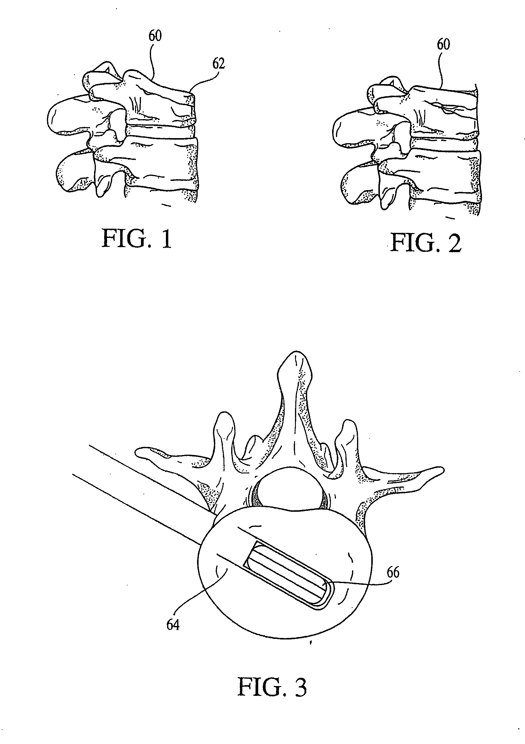
[0090] The invention provides a combination of an implantable distraction device and instrumentation to place the device. The distraction device is detailed in this section by its application to the vertebral compression fracture. FIG. 1 shows a vertebral body 60 having a compression fracture displacing its superior and anterior edge 62. FIG. 2 shows a vertebral body 60 wherein the height has been restored.

The Distraction Device

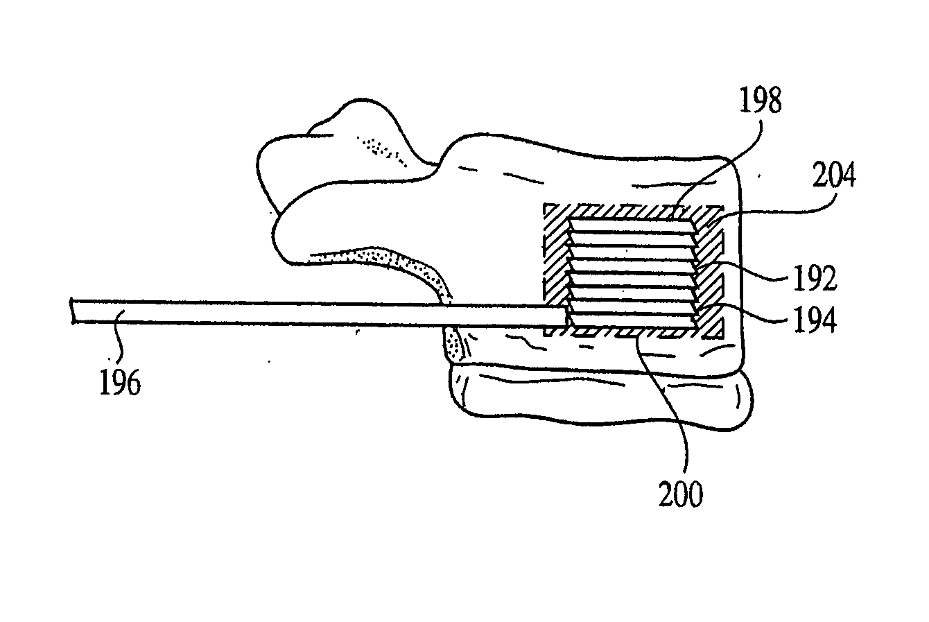
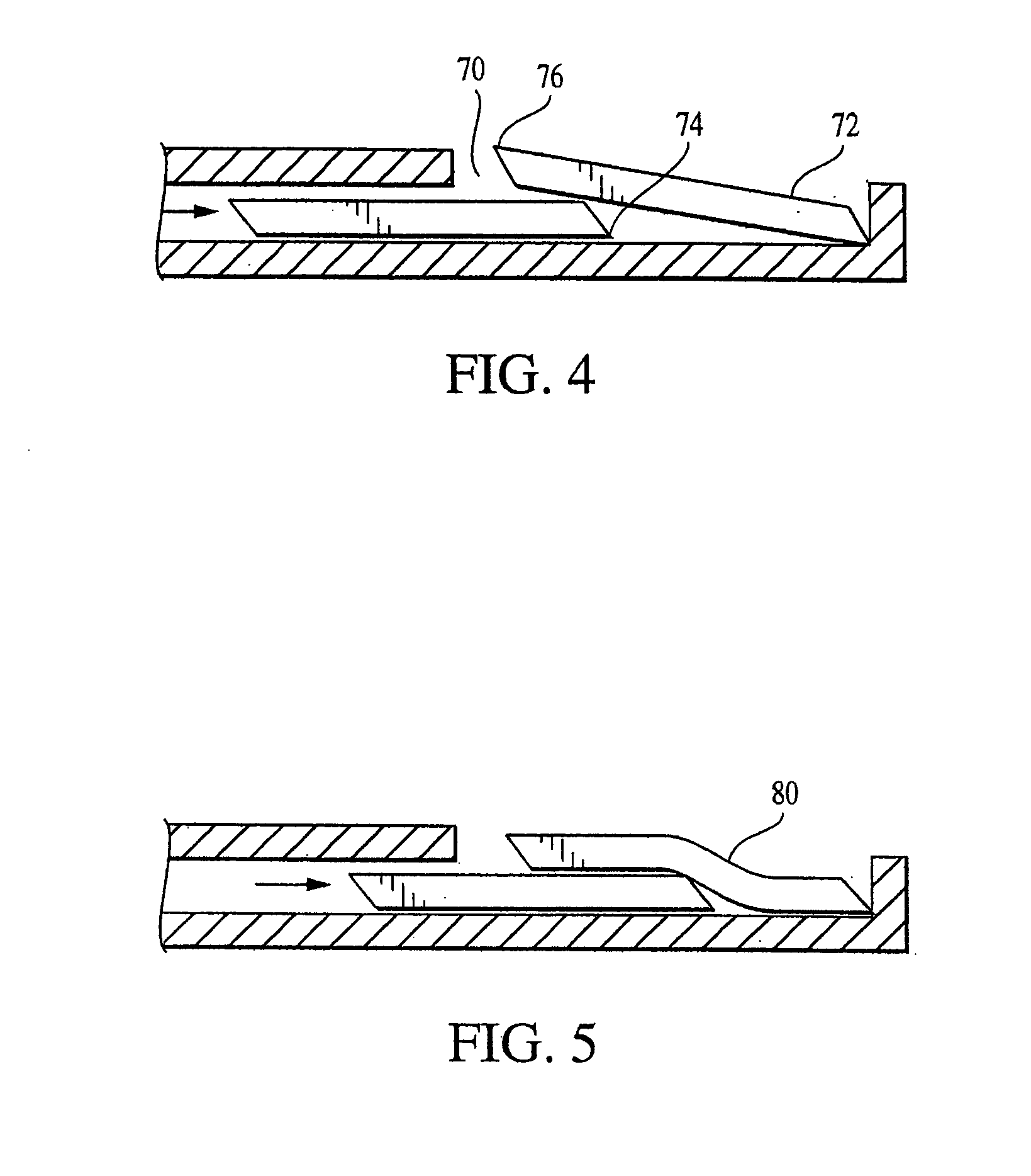
[0091] A plurality of stackable wafers is provided for insertion between two tissues and is delivered to a surgical site along an axis transverse to the axis of distraction. Multiple wafer insertions result in a column of wafers at the surgical site that simultaneously distracts and supports the two tissues.

[0092] The wafers may be formed from a solid form of bone filler material, and / or any other suitable material such as but not limited to implantable grade alloys (including, but not limited to titanium, cobalt chrome, nitinol, or stainless steel), othe...


PUM

PropertyMeasurementUnit
internal diameteraaaaaaaaaa
thicknessaaaaaaaaaa
heightaaaaaaaaaa

Abstract

An apparatus and method for distracting, in a given direction, and supporting two tissue surfaces. A plurality of wafers are consecutively inserted between the two tissue surfaces to create a column of wafers. The column of wafers is oriented between the tissue surfaces so as to expand in the given direction as the wafers are consecutively added to the column.

Description

[0001] This application claims the benefit of priority to U.S. Provisional Application No. ______, filed Mar. 8, 2001.FIELD OF THE INVENTION [0002] The present invention involves the field of surgery, and particularly surgical instruments and methods of using the same. BACKGROUND OF THE INVENTION [0003] A variety of physical conditions involve two tissue surfaces that, for treatment of the condition, need to be distracted from one another and then supported away from one another. Such distraction may be to gain exposure to select tissue structures, to apply a therapeutic pressure to select tissues, to return tissue structures to their anatomic position and form, or in some cases to deliver a drug or growth factor to alter, influence or deter further growth of select tissues. Depending on the condition being treated, the tissue surfaces may be opposed or contiguous and may be bone, skin, soft tissue, or a combination thereof. An optimal treatment method includes distracting and suppo...

Claims


Application Information

Patent Timeline
Patent Type & Authority Applications(United States)
IPC IPC(8): A61B17/02A61B17/70A61B17/58A61B17/88A61F2/00A61F2/28A61F2/30A61F2/44A61F2/46A61L27/00
CPCA61B17/025A61F2310/00359A61B17/8852A61B2017/0256A61F2/28A61F2/44A61F2/442A61F2/4455A61F2/447A61F2/4611A61F2002/30075A61F2002/3008A61F2002/30237A61F2002/30261A61F2002/30385A61F2002/30387A61F2002/30392A61F2002/304A61F2002/30448A61F2002/30449A61F2002/30462A61F2002/30476A61F2002/3049A61F2002/305A61F2002/30599A61F2002/30604A61F2002/30616A61F2002/30772A61F2002/4415A61F2002/4485A61F2002/4627A61F2002/4666A61F2210/0061A61F2220/0025A61F2220/005A61F2220/0075A61F2230/0069A61F2230/0082A61F2250/0063A61F2250/0098A61F2310/00017A61F2310/00023A61F2310/00029A61F2310/00071A61F2310/00203A61F2310/00239A61F2310/00293A61F2310/00353A61F2310/00365Y10S606/907Y10S606/914Y10S606/912A61B17/66A61B17/7097A61F2/4425
Inventor JOHNSON, WESLEY D.LIPSCHULTZ, TYLERWALES, LARRYKIEVAL, ROBERT
Owner SPINEWAVE
Why Eureka
Try Eureka