Optical transmission apparatus and optical transmission system

a transmission apparatus and optical transmission technology, applied in the field of optical transmission apparatus and optical transmission system, can solve the problems of not considering the adjustment technique of the power of branched (dropped) signal lights, excessive etc., to prevent situations, reduce the number of dummy light sources, and increase the power per one wavelength of branched signal lights

Inactive Publication Date: 2005-09-29
FUJITSU LTD
View PDF6 Cites 34 Cited by
  • Summary
  • Abstract
  • Description
  • Claims
  • Application Information

AI Technical Summary

Benefits of technology

[0020] It is another object of the present invention to provide an optical transmission apparatus (optical adding and dropping apparatus) and an optical transmission system wherein the power of branched (dropped) signal lights can be adjusted and the situation can be prevented that the power per one wavelength of branched signal lights becomes excessively high.
[0028] Accordingly, with the present invention, there is an advantage that a transmitter-receiver or a repeater can be used commonly for the trunk line and the branch line. Further, there is another advantage that the power of branched (dropped) signal lights can be adjusted and a situation can be prevented that the power per one wavelength of branched signal lights becomes excessively high. Furthermore, there is a further advantage that the number of dummy light sources can be reduced to one half.

Problems solved by technology

Therefore, if the number of wavelengths (for example, 20 wavelengths) of signal lights to be branched (dropped) is smaller than that (for example, 100 wavelengths) of all signal lights to be transmitted through the trunk line, then the power per one wavelength of the branched signal lights becomes excessively high, and this situation is not preferable.
However, a technique regarding adjustment of the power of branched (dropped) signal lights is not considered at all.

Method used


Image

  • Optical transmission apparatus and optical transmission system
  • Optical transmission apparatus and optical transmission system
  • Optical transmission apparatus and optical transmission system

Examples


Embodiment Construction

[0036] In the following, an optical transmission apparatus (optical add / drop apparatus) and an optical transmission system according to an embodiment of the present invention are described with reference to the drawings.

[0037] In the present embodiment, an optical add / drop apparatus (a branching apparatus of an add / drop type; add drop branching unit, submarine branching apparatus) to be provided in a high-capacity long-distance submarine optical transmission system (optical submarine cable system) as a DWDM optical transmission system is described as an example.

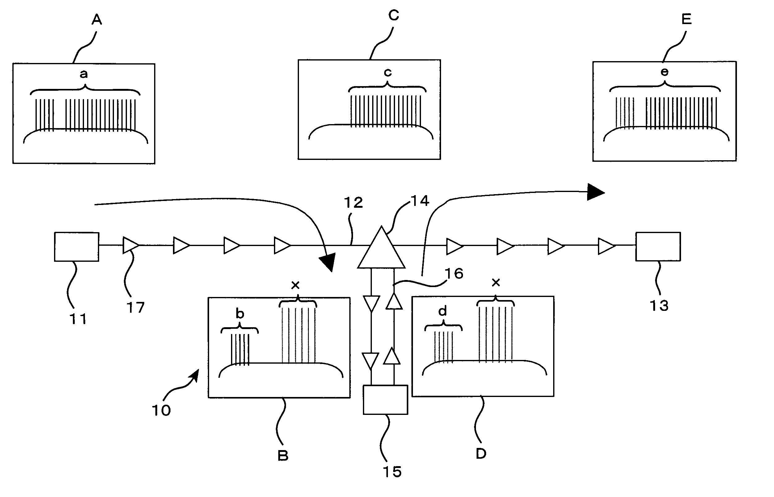
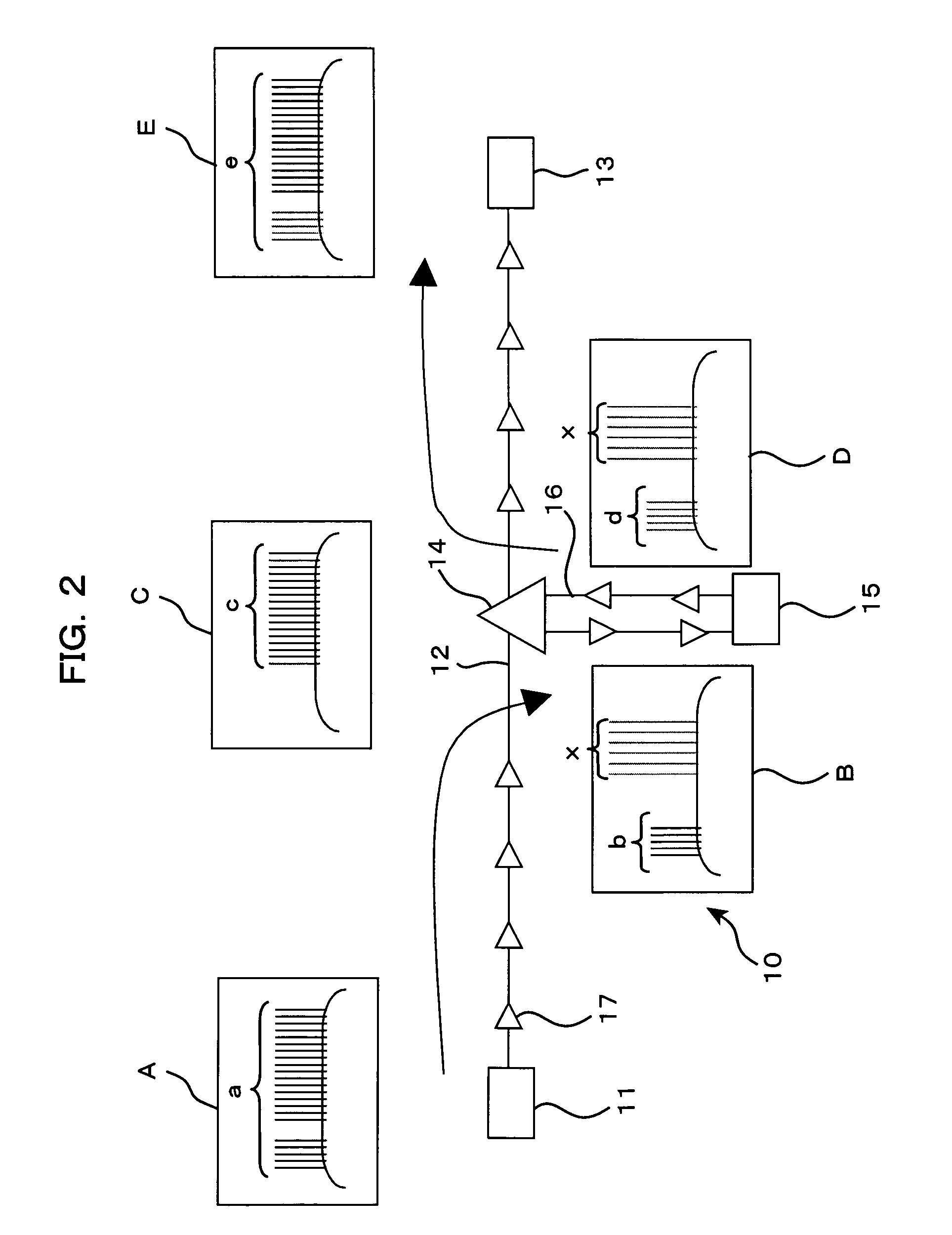
[0038] Referring first to FIG. 2, a high-capacity long-distance submarine optical transmission system (optical submarine cable system) 10 as an optical transmission system includes a transmitting station (terminal) 11 for transmitting wavelength division multiplexed signal lights, and an optical transmission line (trunk line) 12 for connecting the transmitting station 11 and a receiving station 13. The receiving station (te...


PUM


Abstract

An optical transmission apparatus includes a return line for connecting a first transmission line and a second transmission line opposed to the first transmission line in order to make it possible to commonly use a transmitter-receiver or a repeater, for example, between a trunk line and a branch line and prevent a situation that the power of branched signal lights increases excessively. The optical transmission apparatus is configured so that dummy lights inputted together with signal lights to be added to signal lights transmitted through the first transmission line are sent to the second transmission line through the return line and are outputted together with signal lights to be dropped from the second transmission line.

Description

CROSS REFERENCE TO RELATED APPLICATIONS [0001] This application is based on and hereby claims priority to Japanese Application No. 2004-85199 filed on Mar. 23, 2004 in Japan, the contents of which are hereby incorporated by reference. BACKGROUND OF THE INVENTION [0002] 1) Field of the Invention [0003] The present invention relates to an optical transmission apparatus (optical add / drop apparatus) and an optical transmission system suitable for use with a WDM (Wavelength Division Multiplexing) optical transmission system such as, for example, a high-capacity long-distance submarine optical transmission system. [0004] 2) Description of the Related Art [0005] Among WDM optical transmission systems which are being developed at present, for example, those systems (DWDM) which perform a wavelength division multiplexing process for 60 to 150 signal lights of different waves are being popularized in order to implement a high-capacity system. [0006] For example, as shown in FIG. 6, a high-cap...

Claims


Application Information

Patent Timeline
Patent Type & Authority Applications(United States)
IPC IPC(8): H04B10/035H04B10/00H04B10/079H04B10/27H04B10/29H04B10/296H04B10/297H04J14/02
CPCH04B10/2918H04B10/296H04J14/0221H04J14/0213H04J14/022H04J14/0206H04B10/298H04J14/0201
Inventor OTA, KENJI
Owner FUJITSU LTD
Why Eureka
Try Eureka