Ink jet printer

a jet printer and printer body technology, applied in the direction of printing, other printing apparatus, article separation, etc., can solve the problems of scratch resistance, negative effects of light scattering, glossiness of printed images, etc., and achieve the effect of improving image quality

Inactive Publication Date: 2006-08-17
OCE TECH
View PDF8 Cites 2 Cited by
  • Summary
  • Abstract
  • Description
  • Claims
  • Application Information

AI Technical Summary

Benefits of technology

[0007] It is an object of the present invention to improve the image quality of images printed with an ink jet printer of the type indicated above.

Problems solved by technology

This has negative effects on the scattering of light, the scratch resistance and the glossiness of the printed image.

Method used


Image

  • Ink jet printer
  • Ink jet printer
  • Ink jet printer

Examples


Embodiment Construction

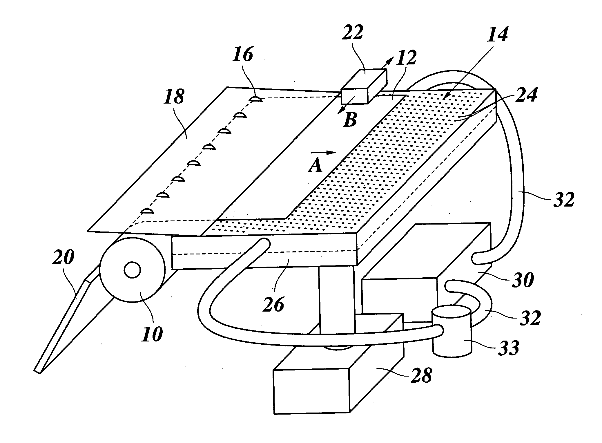
[0020] As is shown in FIG. 1, a hot-melt ink jet printer comprises a platen 10 which is intermittently driven to rotate in order to advance a sheet 12, e. g. a sheet of paper, in a direction indicated by an arrow A over the top surface of a sheet support plate 14. A number of transport rollers 16 are rotatably supported in a cover plate 18 and form a transport nip with the platen 10, so that the sheet 12, which is supplied from a reel (not shown) via a guide plate 20, is paid out through a gap formed between an edge of the cover plate 18 and the surface of the sheet support plate 14.

[0021] A carriage 22 which includes a number of ink jet printheads (not shown) is mounted above the sheet support plate 14 so as to reciprocate in the direction of arrows B across the sheet 12. In each pass of the carriage 22, a number of pixel lines are printed on the sheet 12 by means of the printheads which eject droplets of hot melt ink onto the sheet in accordance with image information supplied to...


PUM


Abstract

An ink jet printer including: a sheet support plate having suction holes formed in a sheet support surface thereof; a sheet advance mechanism adapted to advance a sheet step-wise in a sheet advance direction over the sheet support surface; and an imaging system adapted to form an image by depositing liquid ink on the sheet, the ink being allowed to dry-out while the sheet is advanced over the sheet support plate, wherein the suction holes are arranged such that their influence on the ink drying process is essentially uniform over the whole area of the image.

Description

BACKGROUND OF THE INVENTION [0001] The present invention relates to an ink jet printer including: [0002] a sheet support plate having suction holes formed in a sheet support surface thereof; [0003] a sheet advance mechanism adapted to advance a sheet step-wise in a sheet advance direction over the sheet support surface; and [0004] an imaging system adapted to form an image by depositing liquid ink on the sheet, the ink being allowed to dry-out while the sheet is advanced over the sheet support plate. [0005] In an ink jet printer, a sheet support plate containing suction holes is frequently used for supporting an image receiving sheet and holding the sheet flat on the sheet support plate. By applying a subatmospheric pressure via the suction holes to the bottom side of the sheet, the sheet may be drawn against the top surface of the sheet support plate. The suction holes should be evenly distributed over the surface area of the sheet support plate, so that an essentially uniform suct...

Claims


Application Information

Patent Timeline
Patent Type & Authority Applications(United States)
IPC IPC(8): B65H5/04B65H5/02
CPCB41J11/002B41J11/0085B41J11/06B41J11/00242
Inventor KRUIJT, PIETER G.M.
Owner OCE TECH
Why Eureka
Try Eureka