Ultrasonic sensor having transmission device and reception device of ultrasonic wave

Inactive Publication Date: 2006-09-07
DENSO CORP
View PDF8 Cites 53 Cited by
  • Summary
  • Abstract
  • Description
  • Claims
  • Application Information

AI Technical Summary

Benefits of technology

[0011] The dimensions of the above sensor are minimized, compared with a conventional sensor. Further, a manufacturing cost of the sensor is reduced. Furthermore, a positioning relations

Problems solved by technology

Further, in general, when an ultrasonic sensing device is directly mounted on the bumper of the vehicle, the sensing device cannot detect the distance to the object accurately by a water drop or a dust attac

Method used


Image

  • Ultrasonic sensor having transmission device and reception device of ultrasonic wave
  • Ultrasonic sensor having transmission device and reception device of ultrasonic wave
  • Ultrasonic sensor having transmission device and reception device of ultrasonic wave

Examples


Embodiment Construction

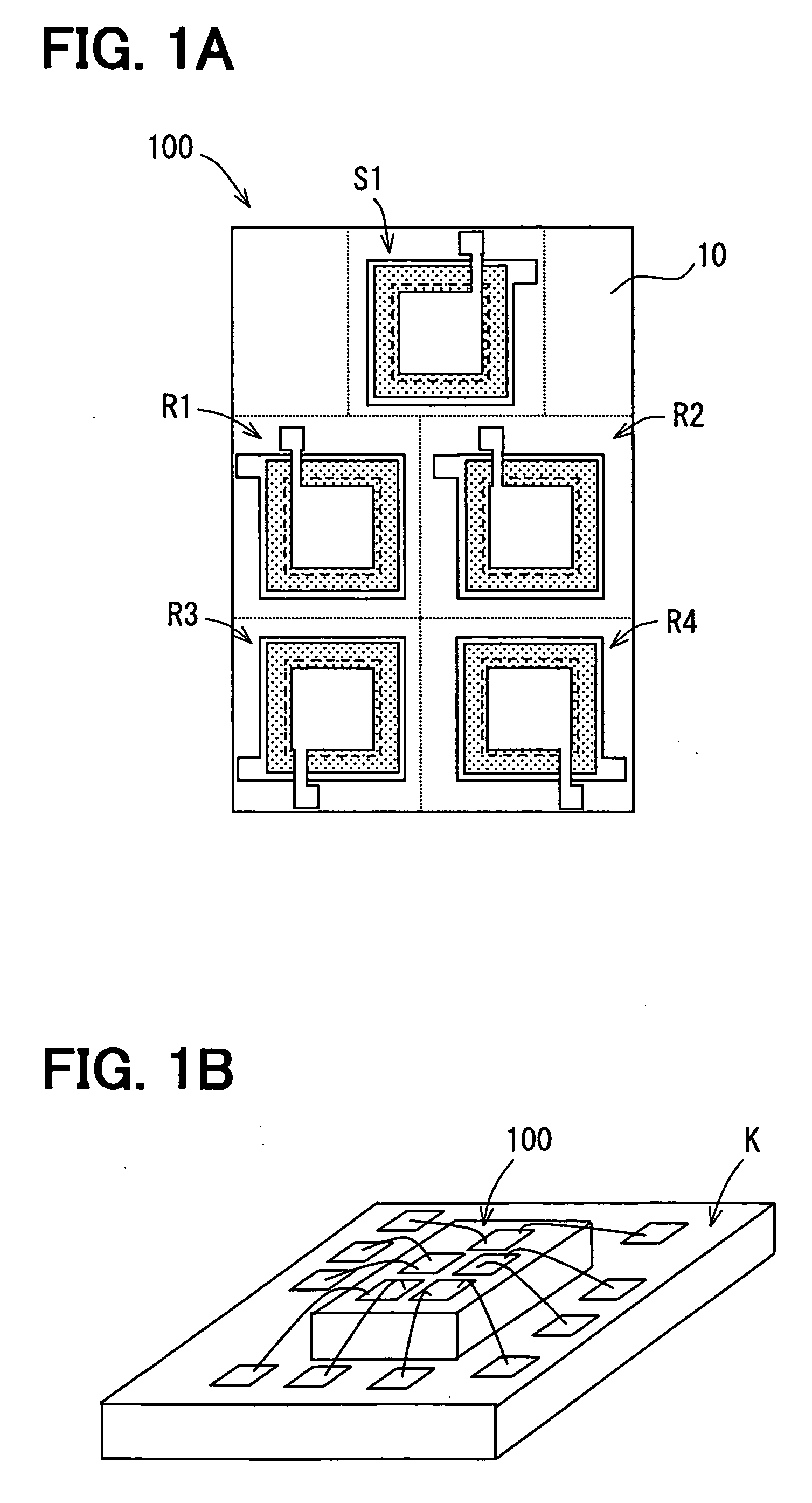
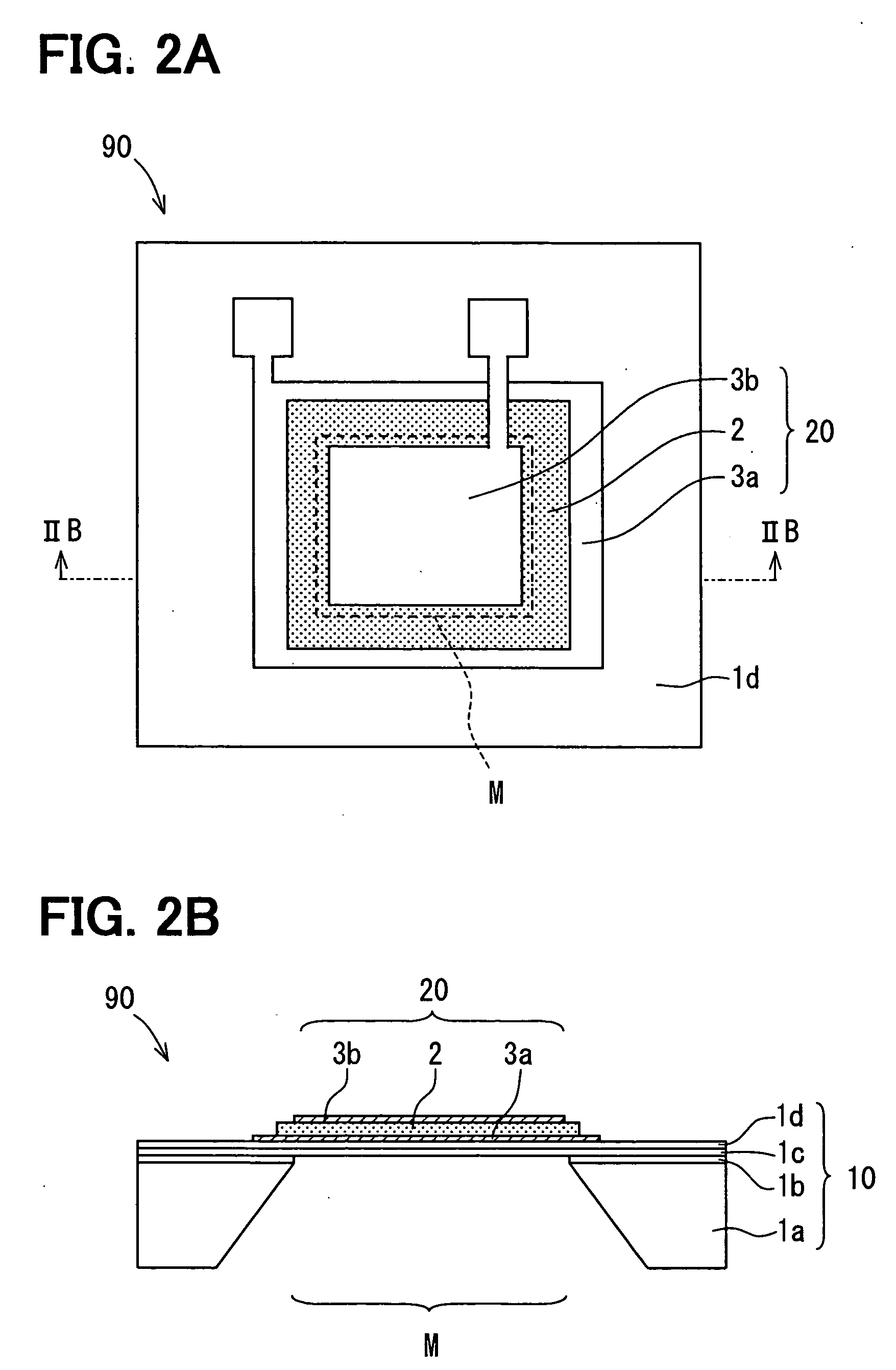
[0030] An ultrasonic sensor 100 according to a preferred embodiment of the present invention is shown in FIGS. 1A and 1B. FIG. 1B shows the sensor 100 mounted on a circuit board K. The sensor 100 includes one transmission device S1 and four reception devices R1-R4, which are integrated on the same semiconductor substrate 10. FIG. 2A shows an ultrasonic element 90 for providing each of the transmission device S1 and the reception device R1-R4.

[0031] The ultrasonic element 90 is similar to the MEMS type ultrasonic element 90R as the reception device shown in FIG. 13A. The transmission device S1 of the ultrasonic element 90 has the same construction of the reception device R1-R4 of the ultrasonic element 90.

[0032] The ultrasonic element 90 is formed of a SOI (i.e., silicon-on-insulator) semiconductor substrate 10. The substrate 10 includes a first semiconductor layer 1a as a supporting layer, an embedded oxide layer 1b, a second semiconductor layer 1c and a protection oxide film 1d. ...


PUM


Abstract

An ultrasonic sensor for detecting an object includes: a substrate; a transmission device for transmitting an ultrasonic wave; a plurality of reception devices for receiving the ultrasonic wave; and a circuit for processing received ultrasonic waves, which are received by the reception devices after the ultrasonic wave transmitted from the transmission device is reflected by the object. The transmission device and the reception devices are integrated into the substrate. The dimensions of the sensor are minimized, and detection accuracy of the sensor is improved.

Description

CROSS REFERENCE TO RELATED APPLICATION [0001] This application is based on Japanese Patent Application No. 2005-56639 filed on Mar. 1, 2005, the disclosure of which is incorporated herein by reference. FIELD OF THE INVENTION [0002] The present invention relates to an ultrasonic sensor. BACKGROUND OF THE INVENTION [0003] An ultrasonic sensor is mounted on an automotive vehicle, for example. The sensor detects a distance between the sensor, i.e., the vehicle and an obstruction when a driver parks the vehicle or when the driver turns the vehicle. The ultrasonic sensor is disclosed in, for example, JP-A-2001-16694. The sensor for detecting the obstruction includes a transmission device and a reception device, which transmits an ultrasonic wave and receives the ultrasonic wave. The sensor may include a transmitting / receiving device. When the transmission device transmits the ultrasonic wave, the ultrasonic wave hits the obstruction. The obstruction reflects the ultrasonic wave; and then,...

Claims


Application Information

Patent Timeline
IPC IPC(8): G01N29/00G01S7/52G01S7/521G01S15/931H04R17/00
CPCG01N2291/02872G01N2291/02881G01S3/808G01S7/521G01S15/42H04R17/00Y10S367/909G01S15/931G01S15/876G01S7/52006
Inventor SUGIURA, MAKIKOYOSHIDA, TAKAHIKO
Owner DENSO CORP
Why Eureka
Try Eureka