Alternator

a technology of alternators and rotating parts, applied in the direction of magnetic circuit rotating parts, magnetic circuit shapes/forms/construction, windings, etc., can solve the problems of cost increase, temperature of rear bearing alone may exceed heat tolerance threshold, etc., and achieve the effect of suppressing temperature increases in rear bearings and increasing outpu

Inactive Publication Date: 2006-09-21
MITSUBISHI ELECTRIC CORP
View PDF3 Cites 22 Cited by
  • Summary
  • Abstract
  • Description
  • Claims
  • Application Information

AI Technical Summary

Benefits of technology

[0015] The present invention aims to solve the above problems and an object of the present invention is to provide an alternator enabling increased output to be achieved by suppressing temperature increases in a rear bearing without relying on increases in cooling airflow rate.
[0017] Using an alternator according to the present invention, temperature increases in the rear bearing can be suppressed, enabling increases in output.

Problems solved by technology

There is a heat tolerance threshold for each of the members, such as 240 degrees Celsius for the stator, 200 degrees Celsius for the diodes, 170 degrees Celsius for the bearings, for example, and there is a risk that the temperature of the rear bearing alone may exceed the heat tolerance threshold.
If such an event occurs, grease in the rear bearing may undergo a heat change, whereby the grease may no longer fulfill its role as a lubricant, the rear bearing may make rattling noises during rotation of the rotor, and although a bearing having an endurance specification of 180 degrees Celsius, for example, can be used in order to prevent that, one problem has been that such measures lead to cost increases.

Method used


Image

  • Alternator
  • Alternator
  • Alternator

Examples


embodiment 1

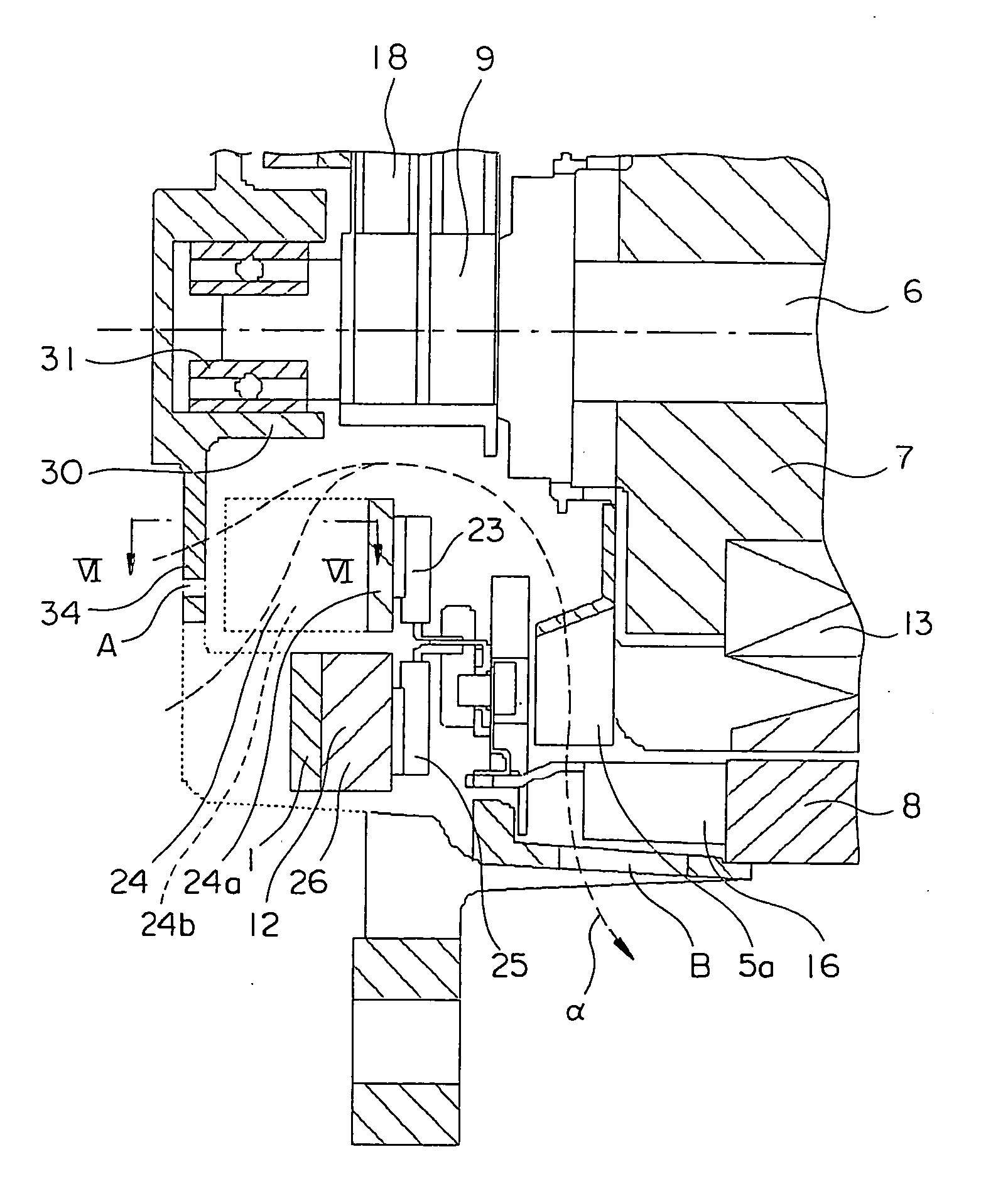
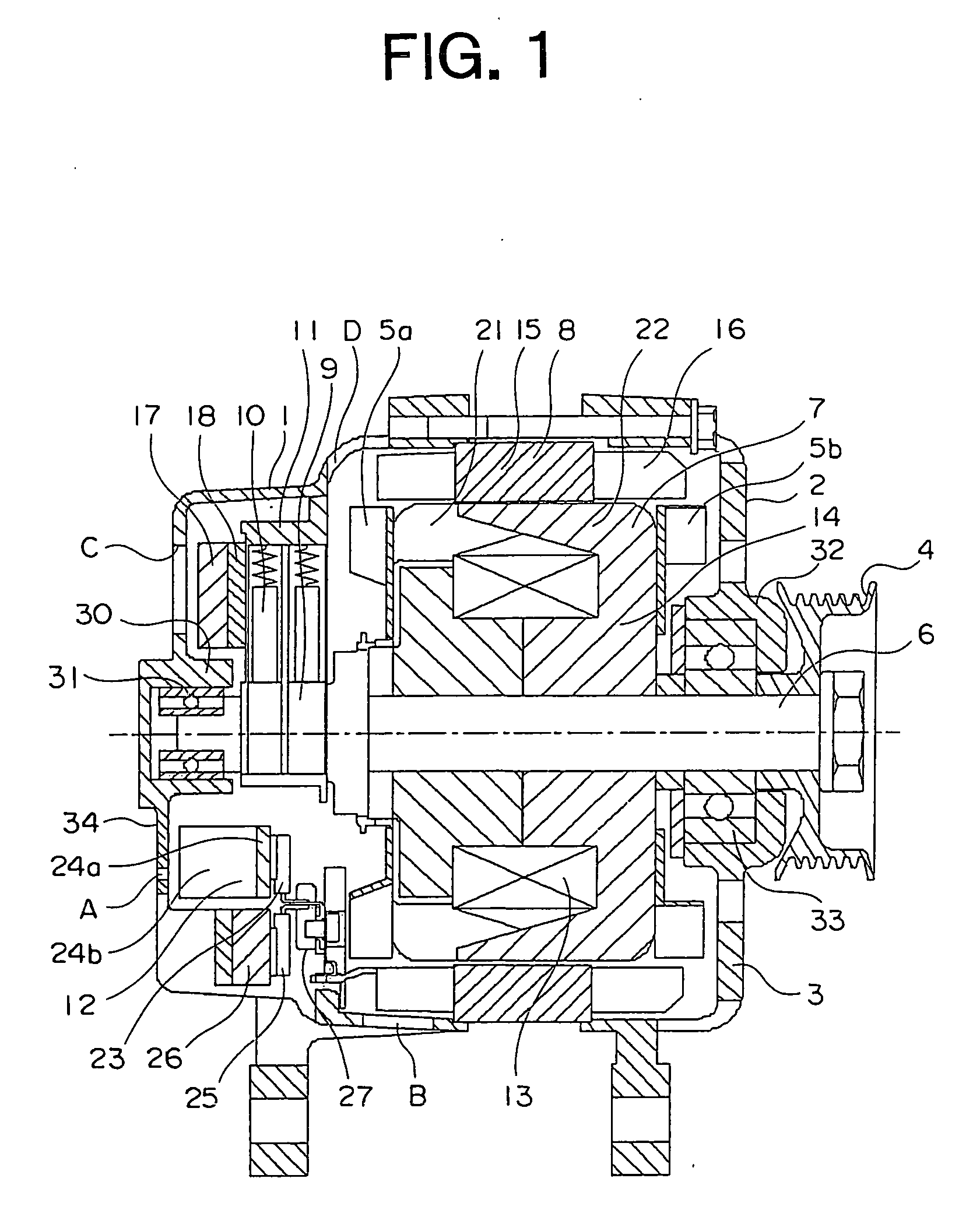
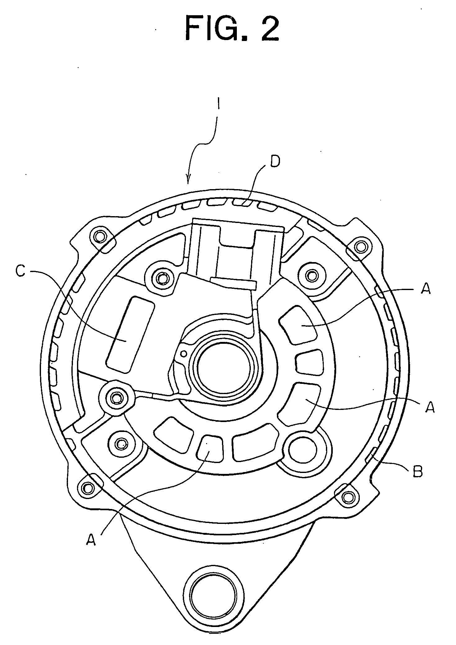
[0029]FIG. 1 is a cross section of an automotive alternator according to the present invention, FIG. 2 is a diagram showing a rear bracket 1 from FIG. 1 when viewed from inside, FIG. 3 is a diagram showing the automotive alternator from FIG. 1 when viewed from a rear bracket end, and FIG. 4 is an overall perspective showing a rectifier 12 from FIG. 1.

[0030] In this automotive alternator, a case 3 is constituted by a rear bracket 1 and a front bracket 2 made of aluminum. A rear bearing 31 is fitted into a rear bearing housing portion 30 of the rear bracket 1. A front bearing 33 is fitted into a front bearing housing portion 32 of the front bracket 2. The front bearing 33 and the rear bearing 31 rotatably support a shaft 6 having a pulley 4 fixed to a first end portion. A Lundell-type rotor 7 is fixed to an intermediate portion of the shaft 6. Slip rings 9 for supplying an electric current to the rotor 7 are fixed to a second end portion of the shaft 6.

[0031] A stator 8 is fixed to ...

embodiment 2

[0054]FIG. 8 is a partial cross section of an automotive alternator according to Embodiment 2 of the present invention.

[0055] This embodiment is similar to the automotive alternator according to Embodiment 1 except for the fact that each of the rear bearing cooling fins 34 is disposed between an adjacent pair of diode cooling fins 24b when the rear bracket 1 is viewed in an axial direction of the shaft 6.

[0056] In this embodiment, because external air turns inward at a downstream end of each of the rear bearing cooling fins 34 and is led between the diode cooling fins 24b, the cooling performance of the rear bearing cooling fins 34, in other words, the cooling performance of the rear bearing 31, is improved compared to that of Embodiment 1.

embodiment 3

[0057]FIG. 9 is a partial cross section of an automotive alternator according to Embodiment 3 of the present invention.

[0058] This embodiment is similar to the automotive alternator according to Embodiment 2 except for the fact that rear bearing cooling fins 34A are disposed so as to extend in an axial direction of the shaft 6 between adjacent pairs of diode cooling fins 24b.

[0059] In this embodiment, although the airflow led between the pairs of diode cooling fins 24b is significantly reduced, which lowers the cooling performance of the positive-side heat sink 24, the surface area of the rear bearing cooling fins 34A is increased and the cooling performance of the rear bearing 31 is improved significantly, enabling the temperature of the rear bearing 31 to be significantly reduced.


PUM


Abstract

An automotive alternator according to the present invention includes: a shaft having an end portion rotatably supported by a rear bearing housed inside a rear bearing housing portion of a rear bracket; a rectifier for converting an alternating current into a direct current; and a first centrifugal fan for cooling a rotor, a stator, and the rectifier by sucking in external air through a suction inlet in the bracket when the rotor rotates, the rectifier has a positive-side heat sink for cooling a plurality of positive-side diodes, the suction inlet is formed in a vicinity of the rear bearing housing portion, and a plurality of rear bearing cooling fins extending in a direction perpendicular to the shaft are formed on a side of the suction inlet near the rear bearing housing portion.

Description

BACKGROUND OF THE INVENTION [0001] 1. Field of the Invention [0002] The present invention relates to an alternator in which a rotor, a stator, and a rectifier are cooled by external air sucked in through a suction inlet of a rear bracket by rotation of a fan fixed to the rotor. [0003] 2. Description of the Related Art [0004] Conventionally, alternators are known that include: a case constituted by a rear bracket and a front bracket; a shaft having a first end portion disposed in a rear bearing housing portion of the rear bracket and a second end portion rotatably supported in a front bearing disposed in a front bearing housing portion of the front bracket; a rotor fixed to the shaft; a stator constituted by: a stator core fixed to an inner wall surface of the case; and a stator coil configured by winding conducting wire onto the stator core; a rectifier disposed inside the rear bracket and electrically connected to the stator coil so as to convert alternating current generated in th...

Claims


Application Information

Patent Timeline
Patent Type & Authority Applications(United States)
IPC IPC(8): H02K9/00
CPCH02K5/1732H02K5/18H02K11/046H02K11/05
Inventor IKUTA, HIROYAKASHIHARA, TOSHIAKI
Owner MITSUBISHI ELECTRIC CORP
Why Eureka
Try Eureka