Floating seal assembly for a trocar

a floating seal and trocar technology, applied in trocars, medical devices, other medical devices, etc., can solve the problems of damage to previously known sealing mechanisms, and achieve the effect of sufficient flexibility and elasticity, sufficient flexibility and/or elasticity

Inactive Publication Date: 2006-10-05
PILLING WECK INC
View PDF28 Cites 32 Cited by
  • Summary
  • Abstract
  • Description
  • Claims
  • Application Information

AI Technical Summary

Benefits of technology

[0023] In that inner sleeve assumes an “interruptive disposition” between the sealing structure and a medical instrument entering the seal housing, the inner sleeve is preferably formed from a material resistant to puncturing, tearing or like damage by the leading end of the instrument. However, the inner sleeve should also demonstrate sufficient flexibility and elasticity for the reasons set forth above. As such, the material from which the inner sleeve is formed may have a durometer reading such as in the range of generally about 80 durometers. In contrast, the seal structure should demonstrate sufficient elasticity or like structural and performance characteristics to accomplish a substantially fluid tight seal between the periphery of the sealing aperture and the exterior surface of the instrument. Accordingly, the durometer reading of the seal structure will preferably be, but does not have to be, lower than that of the inner sleeve, in order that it demonstrates sufficient flexibility and/or elasticity to accomplish an effective seal with the entering instrument. As indicated above, and described in greater detail hereinafter, sealing engagement between the instrument and the seal member prevents or at least minimizes the escape of insuflation gas when the instrument is present in the trocar and extends through the seal member.
[0024] Yet another feature of this preferred embodiment of the seal member includes the interior or exposed face of the inner sleeve member having an irregular surface configuration. Such an irregular surface configur

Problems solved by technology

This angled or skewed orientation of the instrument as it is being introduced into the trocar has been known to cause damage to previously known sealing mechanisms within the trocar, du

Method used


Image

  • Floating seal assembly for a trocar
  • Floating seal assembly for a trocar
  • Floating seal assembly for a trocar

Examples


Embodiment Construction

)

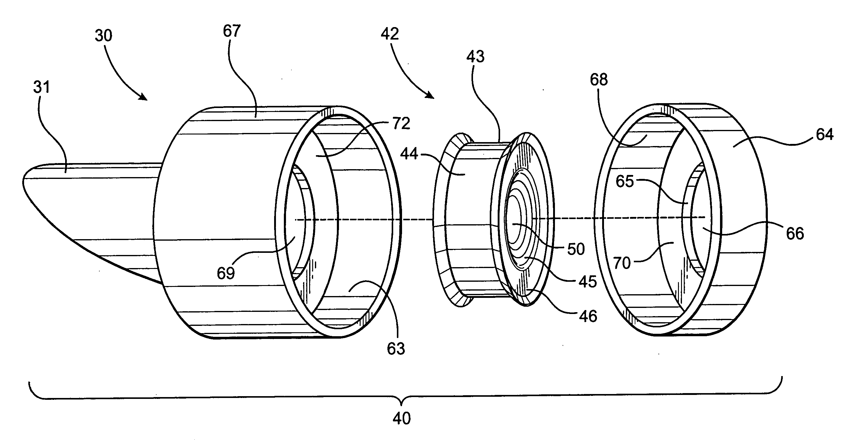
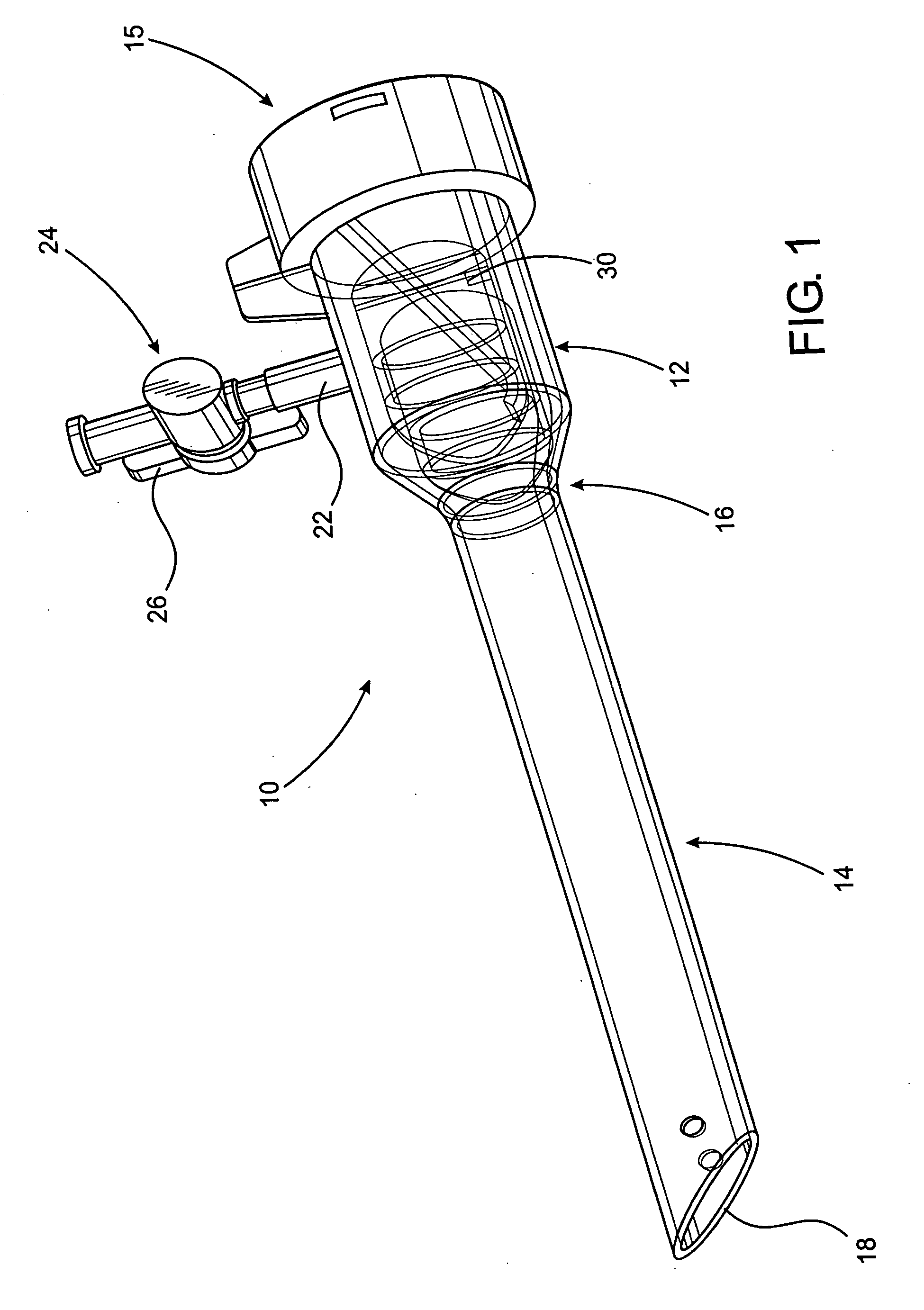
[0054] The present invention is directed to a seal assembly that is primarily structured to be used with a trocar, as shown in FIGS. 1 and 10, or a like device associated with the introduction of medical instruments through anatomical tissues and into the body cavity of a patient, such as during laparoscopic surgery. It is to be understood at the outset that the present invention is susceptible of embodiment in different forms. While there is shown in the drawings and will be described in detail herein at least one specific embodiment, it is with the understanding that the present disclosure is to be considered as an exemplification of the principles of the invention which should not limit the invention to the embodiment or embodiments illustrated.

[0055] With initial reference to FIG. 1, there is illustrated one possible type of a trocar assembly, indicated generally as 10, with which the seal assembly of the present invention may be used. The present invention is, however, readil...


PUM


Abstract

A seal assembly used in combination with a trocar assembly and disposed and structured to establish sealing engagement with the exterior surface of medical instrument introduced into the trocar assembly so as to maintain adequate insufflation pressure within a body cavity accessed by the trocar assembly. The seal assembly includes a seal member unconnected to and freely moveable, at least laterally, within a seal chamber of the trocar assembly. The seal member and the seal chamber are cooperatively dimensioned to maintain one or more outer peripheral surfaces of the seal member in surrounding, sealing relation to one or both of the inlet and outlet ports of the seal chamber thereby eliminating or reducing the escape of insuflation gas through the trocar assembly when an instrument is present therein.

Description

CLAIM OF PRIORITY [0001] This application is a continuation-in-part of a previously filed application, having Ser. No. 10 / 424,564 and a filing date of Apr. 28, 2003, which is set to mature into U.S. Pat. No. 7,011,314 on Mar. 14, 2006, which was based on and includes a claim of priority pursuant to 35 U.S.C. Section 119(e) to a prior filed provisional patent application, namely, that having Ser. No. 60 / 376,033 and a filing date of Apr. 26, 2002, both of which are incorporated in their entireties herein by reference.BACKGROUND OF THE INVENTION [0002] 1. Field of the Invention [0003] This invention relates to a seal assembly of the type normally used with a trocar or like device structured to introduce medical instruments into the body cavity of a patient for purposes of performing surgery. The seal assembly includes a seal member freely movable within a chamber of a seal housing, whether formed as part of the trocar or attached thereto, and generally overcomes recognized disadvantage...

Claims


Application Information

Patent Timeline
IPC IPC(8): F16L5/02A61B17/34A61M31/00
CPCA61B17/3462A61B2017/3464A61B17/3474
Inventor MCFARLANE, RICHARD H.
Owner PILLING WECK INC
Why Eureka
Try Eureka