Non-lethal electrical discharge weapon having a bottom loaded cartridge

a non-lethal, cartridge technology, applied in the direction of weapons, electrical equipment, ammunition, etc., can solve the problems of ineffective first “shot”, increased agitation of assailant, and increased risk of attack by officer, so as to reduce the time required for a reload cycle and reduce the load time

Inactive Publication Date: 2006-10-12
PARK SAMUEL SUNG WAN
View PDF9 Cites 14 Cited by
  • Summary
  • Abstract
  • Description
  • Claims
  • Application Information

AI Technical Summary

Benefits of technology

[0010] With a bottom loading system, once the weapon is discharged, one finger of the weapon holding hand can disengage the latch holding the cartridge. This allows the cartridge to fall to the ground by gravity. Only one hand is required to unload the weapon. This significantly reduces the time required for a reload cycle and allows the free contralateral hand to have the next cartridge in waiting, further decreasing the load time.

Problems solved by technology

There can be occasions when the number of steps or distinct body motions and resulting reload time can become critical to the safety of a police officer and even to an assailant who may be threatening an officer.
When an office has to reload his non-lethal electrical discharge weapon, it usually means that for one reason or another his or her first “shot” has been ineffective.
Often, the assailant becomes more agitated and more likely to attack the officer after a failed attempt to subdue him or her has occurred.

Method used


Image

  • Non-lethal electrical discharge weapon having a bottom loaded cartridge
  • Non-lethal electrical discharge weapon having a bottom loaded cartridge
  • Non-lethal electrical discharge weapon having a bottom loaded cartridge

Examples


Embodiment Construction

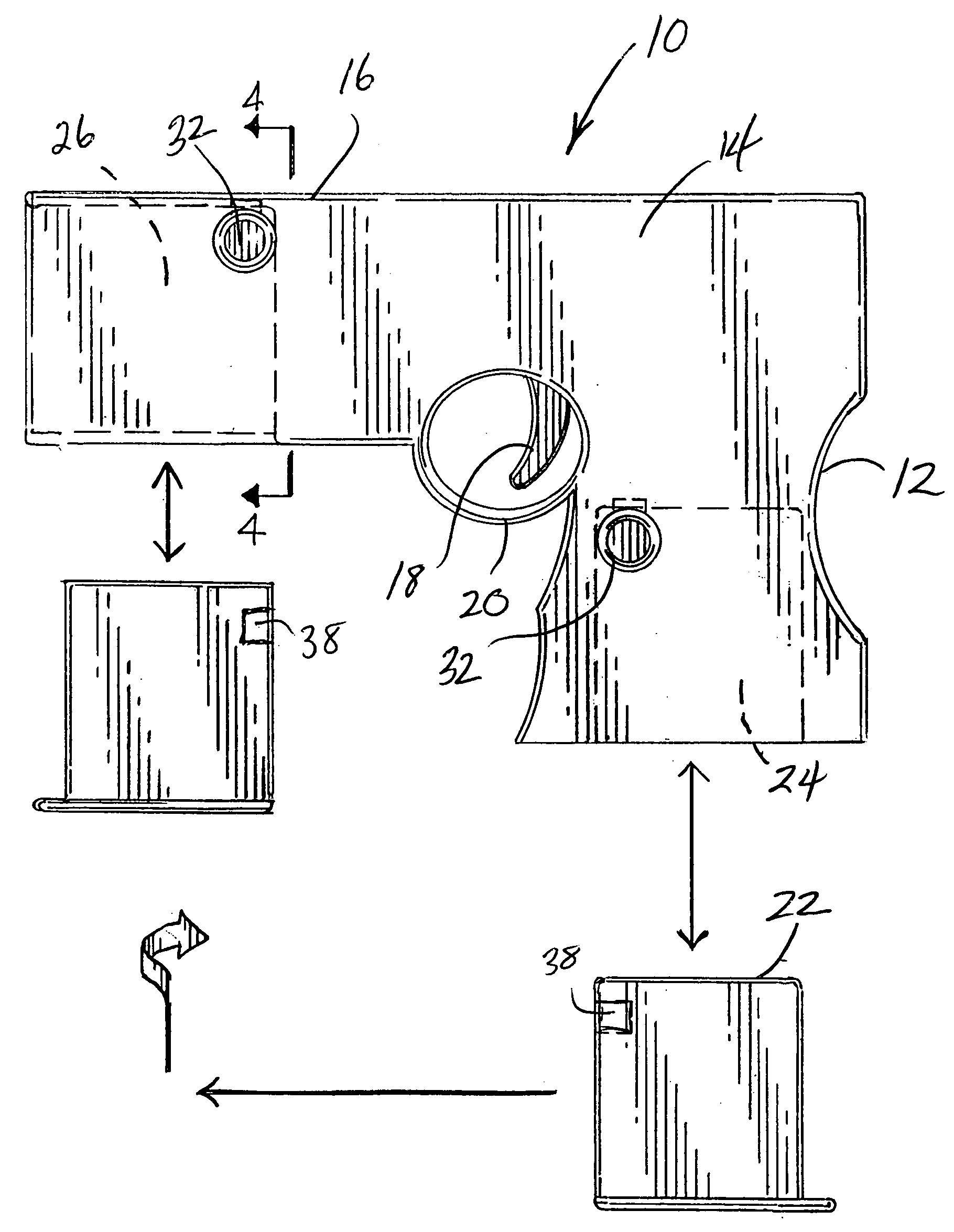
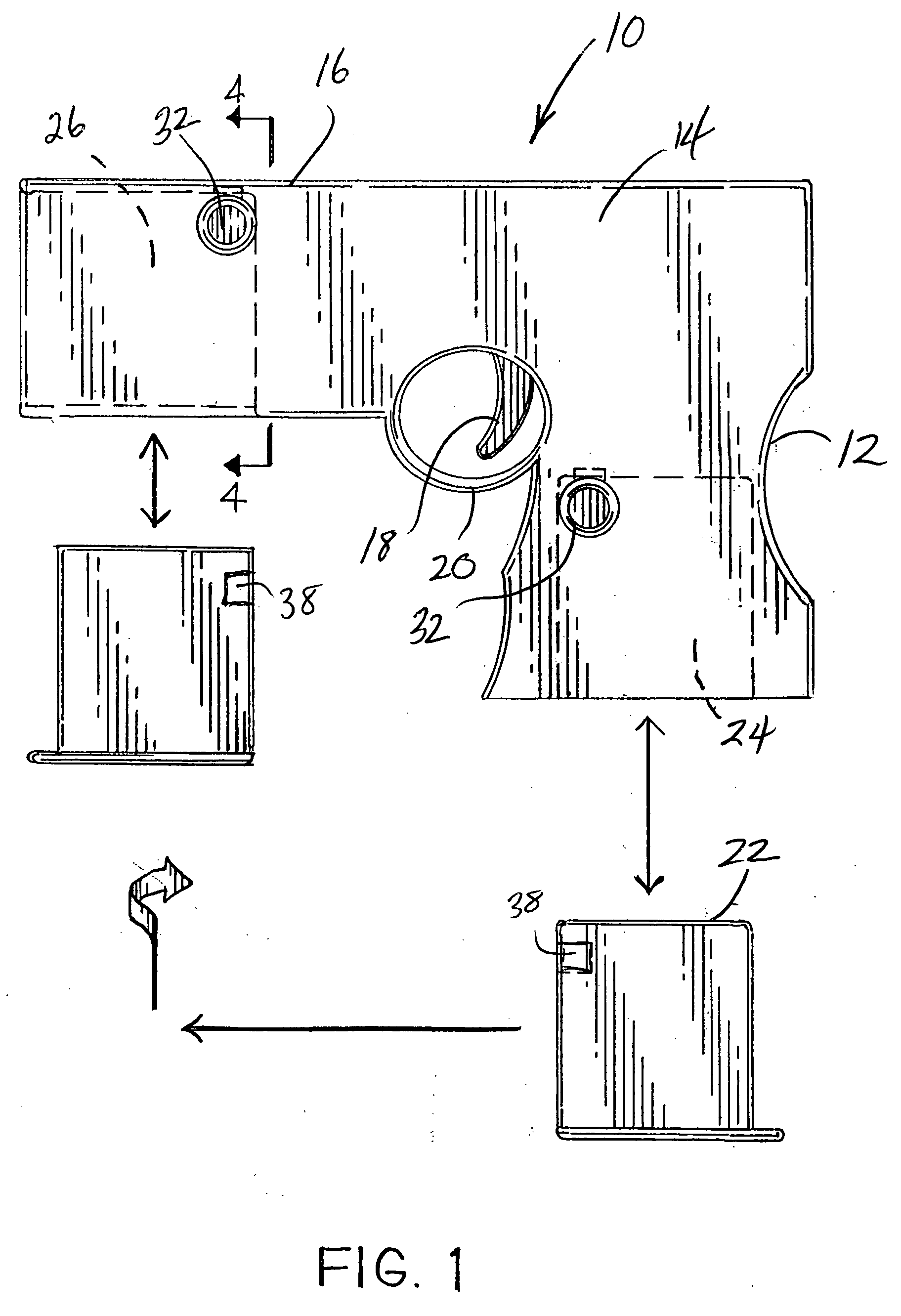
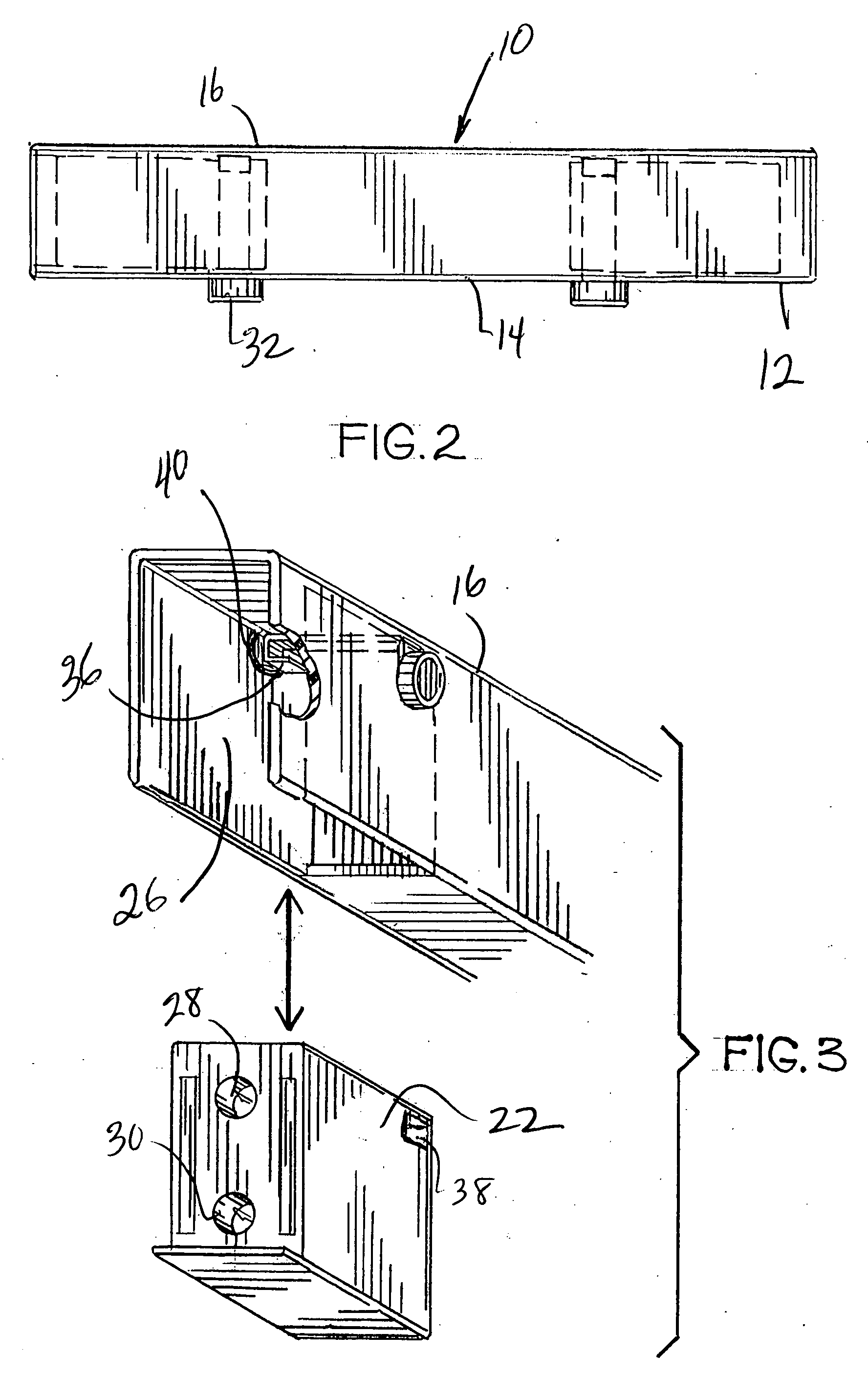
[0020] Referring to the accompanying drawings and to FIGS. 1-3 in particular, it will be seen that a Taser™-type weapon 10 comprises a handle portion 12, a body portion 14 and a barrel portion 16. Also provided are an actuating trigger switch 18 within a trigger guard 20. Handle portion 12 provides a spare cartridge bay 24 to receive a spare cartridge 22. Barrel portion 16 terminates in a cartridge chamber 26 designed to receive a cartridge 22 for activation of the weapon 10. Cartridge 22 has a pair of apertures 28 and 30 through which wire-tethered darts (not shown) may be propelled toward a remote target upon activation of the weapon.

[0021] As seen best in FIG. 3, chamber 26 has two contiguous openings, one in front of the weapon and one below the weapon. In this manner, cartridge 22 is readily inserted into chamber 26 from below barrel portion 16 in an upward motion as depicted in FIG. 3. The cartridge 22 will, of course, have appropriately positioned electrical contacts (not sh...


PUM


Abstract

The present invention comprises a pistol-shaped Taser™-type weapon wherein the cartridge containing a pair of the wire-tethered darts is loaded into the cartridge receiving chamber from beneath the weapon, that is, in an upward movement of the cartridge with the weapon pointed toward the target. This type of loading is referred to herein as a “bottom loading” mechanism or system. The bottom loading mechanism of the present invention has significant advantages over conventional cartridge loading designs. One advantage is reduced reload time.

Description

BACKGROUND OF THE INVENTION [0001] 1. Field of the Invention [0002] The present invention relates generally to an electrical discharge weapon having replaceable cartridges, each carrying a pair or wire-tethered darts that are propelled toward a remote target for imparting a temporarily disabling electrical shock. The invention relates more specifically to such a weapon and cartridges wherein the cartridges may be bottom loaded into the weapon's firing chamber to significantly reduce reloading time after a cartridge has been spent. [0003] 2. Background Art [0004] Electrical discharge weapons capable of firing wire tethered darts at remote targets have become useful non-lethal alternatives for police officers to subdue uncooperative and potentially dangerous subjects. Typically, such wire-tethered darts and a suitable propulsion mechanism are contained in replaceable cartridges which are loaded into the weapon for firing. Once the cartridges are spent, they may be removed and replaced...

Claims


Application Information

Patent Timeline
Patent Type & Authority Applications(United States)
IPC IPC(8): F41C9/00
CPCF41H13/0025
Inventor PARK, SAMUEL SUNG WAN
Owner PARK SAMUEL SUNG WAN
Why Eureka
Try Eureka