Flat radially interacting electric drive and a method of the manufacturing the same

Inactive Publication Date: 2006-10-26
INDAL DESIGN LAB
View PDF7 Cites 21 Cited by
  • Summary
  • Abstract
  • Description
  • Claims
  • Application Information

AI Technical Summary

Benefits of technology

[0017] Accordingly, it is an object of the present invention to provide a flat radially interacting electric drive and a method of manufacturin

Problems solved by technology

The known device is not easy in manufacturing, the biggest difficulty being manufacturing of disk-shaped rotors with magnetic poles of alternating polarity.
Cooling is important because if left unchecked, heat can cause electronic devices to malfunction during use or lead to premature device failure.
Additionally, improved processors require larger power supplies and auxiliary components that generate increased amounts of heat and require improved systems for heat removal.
The trend toward smaller and thinner electronic devices having larger, faster processors renders the traditional heat removal cooling systems inadequate for several reasons.
However, such arrangement cause a vibration of the flat stator and magnetized rotor due to a rise of oscillation forces in a direction perpendicular to the planes of the flat stator and the magnetized rotor.
In one's turn the vibration generates an increasing sound l

Method used


Image

  • Flat radially interacting electric drive and a method of the manufacturing the same
  • Flat radially interacting electric drive and a method of the manufacturing the same
  • Flat radially interacting electric drive and a method of the manufacturing the same

Examples


Embodiment Construction

[0047] Preferred embodiments of the present invention will be described in detail below with reference to the accompanying drawings.

[0048]FIGS. 1-18 show embodiments of the present invention.

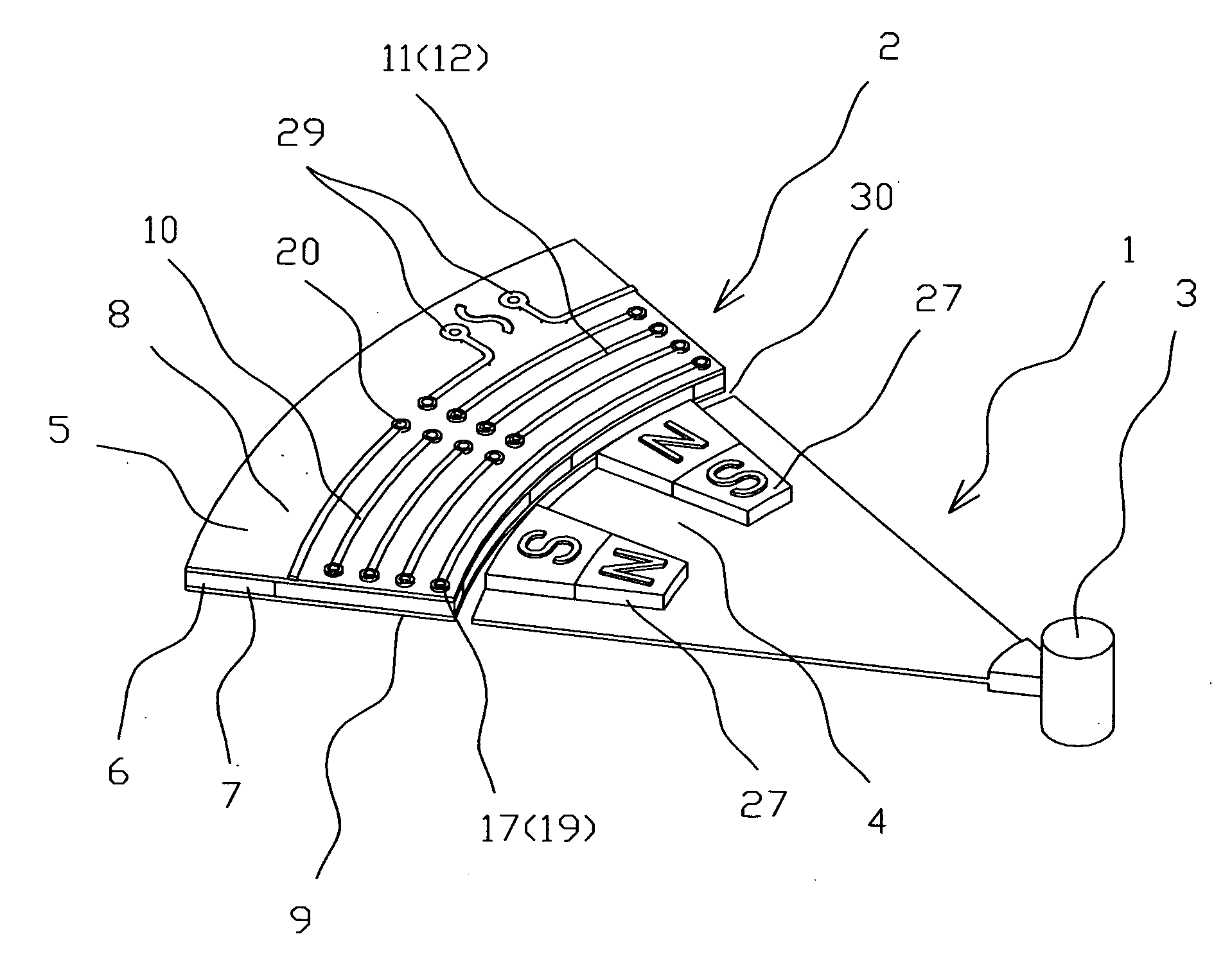
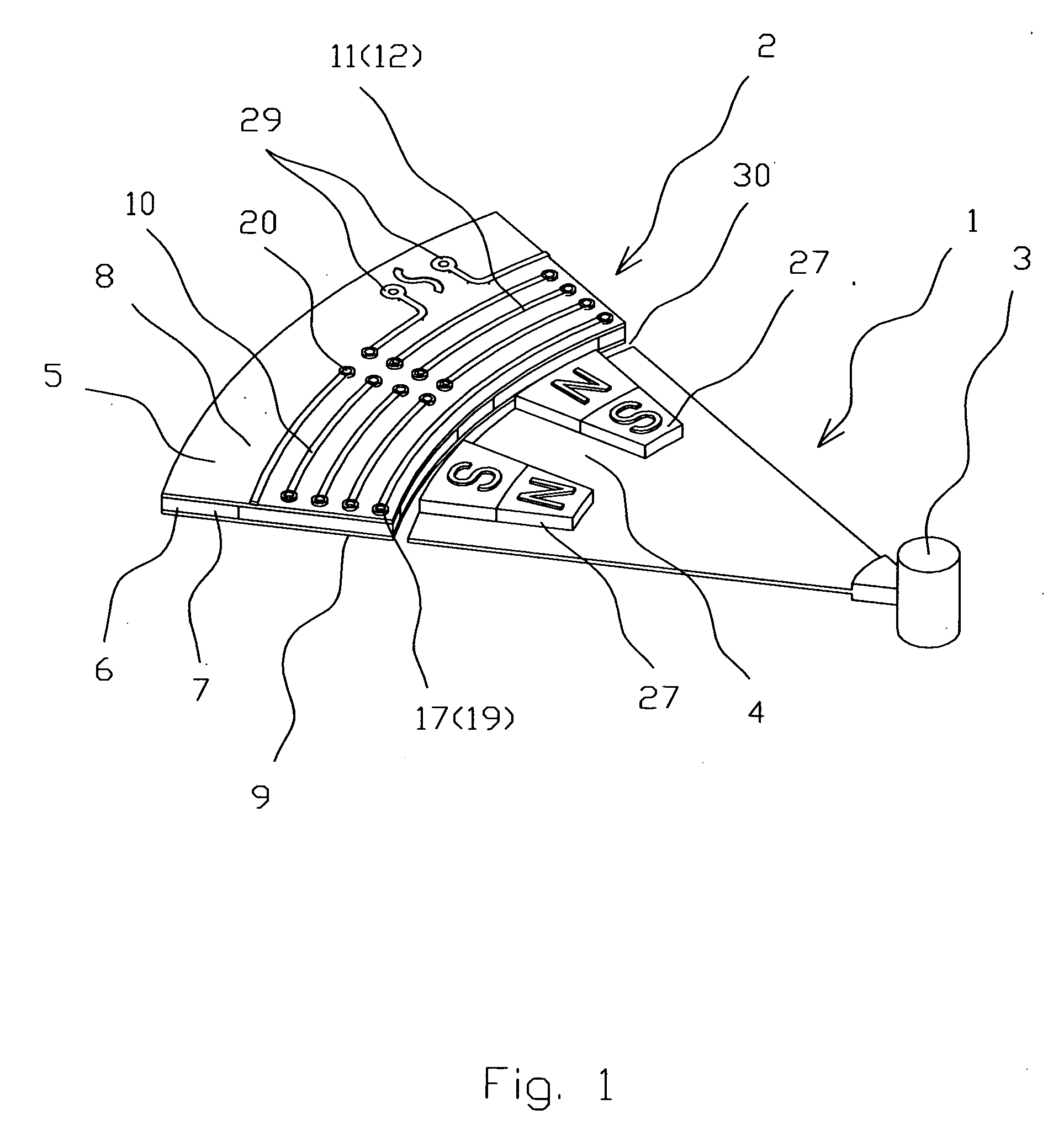
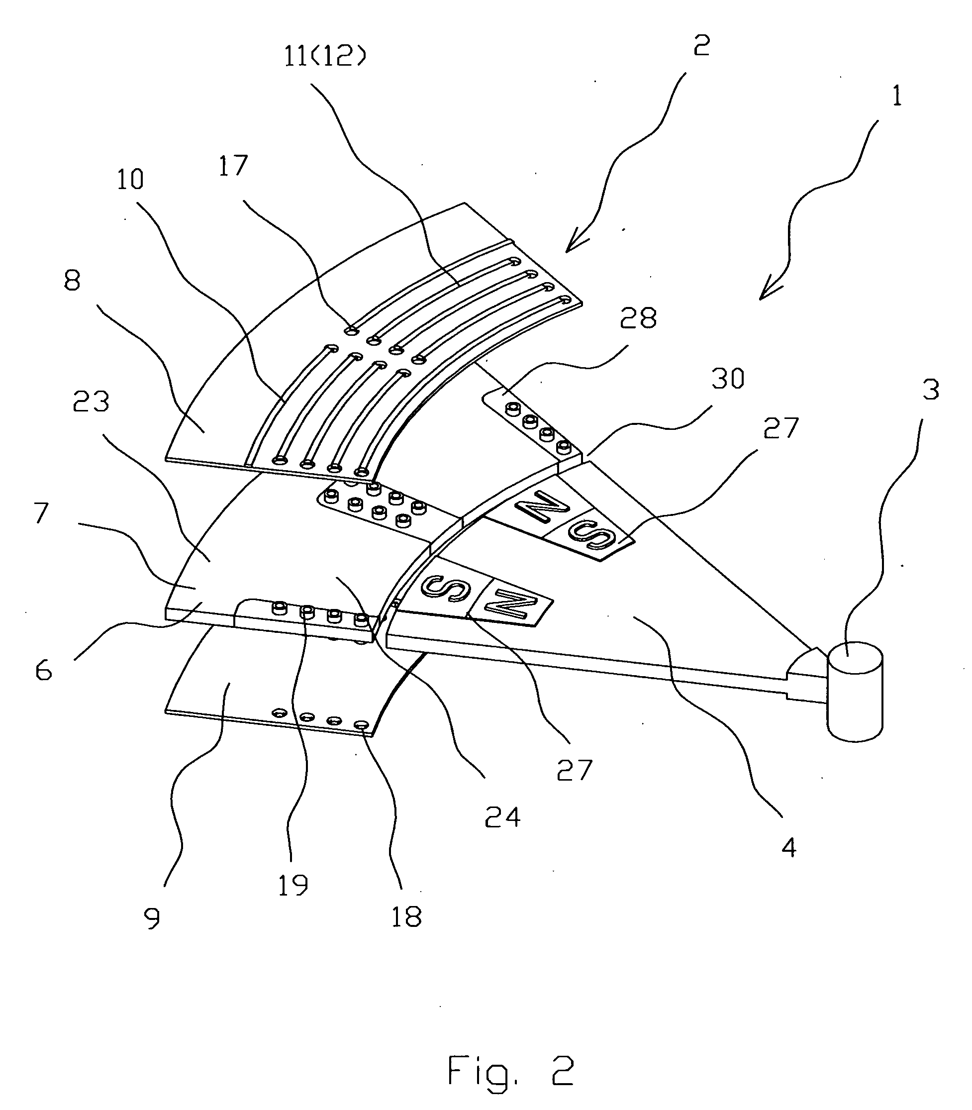
[0049] The flat radially interacting electric drive 1 (FIGS. 1-18) comprises a flat stator 2, an axle 3 and a magnetized flat rotor 4. The stator 2 made like a composite structure 5 comprises a layer 6 made of ferromagnetic material serving like a stator core 7 and placed within two layers 8 and 9 of circuit boards. The layer 6 made of ferromagnetic material could be made from silicon steel.

[0050] The first 8 of said layers of circuit board comprises circumferentially arrayed groups 10 of traces 11 that are unidirectional segments 12 of zigzag lines 13 with a path 14 directed radially, while the second 9 of said layers of circuit board comprises circumferentially arrayed groups 15 of traces 11a which in transparent view are opposite unidirectional segments 16 of the same zigzag lines 13.

[005...


PUM


Abstract

A flat radially interacting electric drive comprises a flat stator, an axle and a magnetized flat rotor. The flat stator comprises a stator core made of silicon steel and placed within two layers of circuit boards. The circuit boards layers comprise circumferentially arrayed traces that are corresponding unidirectional segments of spatial continuous zigzag lines serving like coils with magnetic axes being directed radially. The coils electrically connected in a series way thus form a stator winding with alternated polarity coils. The flat rotor comprises circumferentially arrayed alternatively magnetized flat magnets with radially directed magnetic axes.

Description

CROSS REFERENCE TO RELATED APPLICATIONS [0001] The present application claims the benefit of priority of U.S. Provisional Patent Application No. 60 / 674.755, filed Apr. 26, 2005 for Edward Lopatinsky et al. the entire content of which is incorporated herein by reference.FIELD OF THE INVENTION [0002] The present invention relates generally to brushless DC electric drives. More particularly, the present invention relates to flat type electric drives. The present invention is particularly, but not exclusively, useful for blowers of cooling systems for regulating the temperature of electronic components. BACKGROUND OF THE INVENTION [0003] Well-known are electric drives of end-face rotor-stator interaction type, where the rotor is a disk, on the end surfaces whereof permanent magnets of alternating polarity are located over the circumference. The stator of such machines is made in the shape of a disk (ring), installed coaxially with the rotor thus the stator and the rotor located in diffe...

Claims


Application Information

Patent Timeline
IPC IPC(8): H02K21/12H02K1/00H02K3/04
CPCH02K3/47H02K15/02H02K21/22H02K21/12H02K21/14H02K15/061
Inventor LOPATINSKY, EDWARDFEDOSEYEV, LEVSCHAEFER, DANIEL
Owner INDAL DESIGN LAB
Why Eureka
Try Eureka