Display device, and driving method and electronic apparatus of the display device

a display device and driving method technology, applied in static indicating devices, instruments, electroluminescent light sources, etc., can solve the problems of reducing the reliability of light-emitting elements, increasing power consumption, and causing false contours of display devices, so as to reduce false contours, improve display quality, and clear image

Active Publication Date: 2006-11-02
SEMICON ENERGY LAB CO LTD
View PDF4 Cites 91 Cited by
  • Summary
  • Abstract
  • Description
  • Claims
  • Application Information

AI Technical Summary

Benefits of technology

[0028] In view of the foregoing problems, it is an object of the invention to provide a display device and a driving method thereof, which is capable of reducing pseudo contours with a small number of subframes.
[0041] The invention enables a reduction of pseudo contours. Therefore, display quality can be improved to provide a clear image. In addition, the duty ratio is improved as compared to the case of using the conventional double-speed frame method, which results in a suppressed voltage applied to a light-emitting element. Thus, power consumption can be reduced and degradation of the light-emitting element can be suppressed.

Problems solved by technology

It is known that display defects called pseudo contours (or false contours) occur when using such a time gray scale method.
Thus, in order to keep the same average luminance as in the case of not using the double-speed frame method, a voltage applied to a light emitting-element is required to be increased, which results in the increased power consumption, lower reliability of the light-emitting element, and the like.

Method used


Image

  • Display device, and driving method and electronic apparatus of the display device
  • Display device, and driving method and electronic apparatus of the display device
  • Display device, and driving method and electronic apparatus of the display device

Examples


embodiment mode 1

[0120] In this embodiment mode, description is made on an example where the driving method of the invention is applied to a case of displaying 5-bit gray scales (32 gray scales) and a case of displaying 6-bit gray scales (64 gray scales).

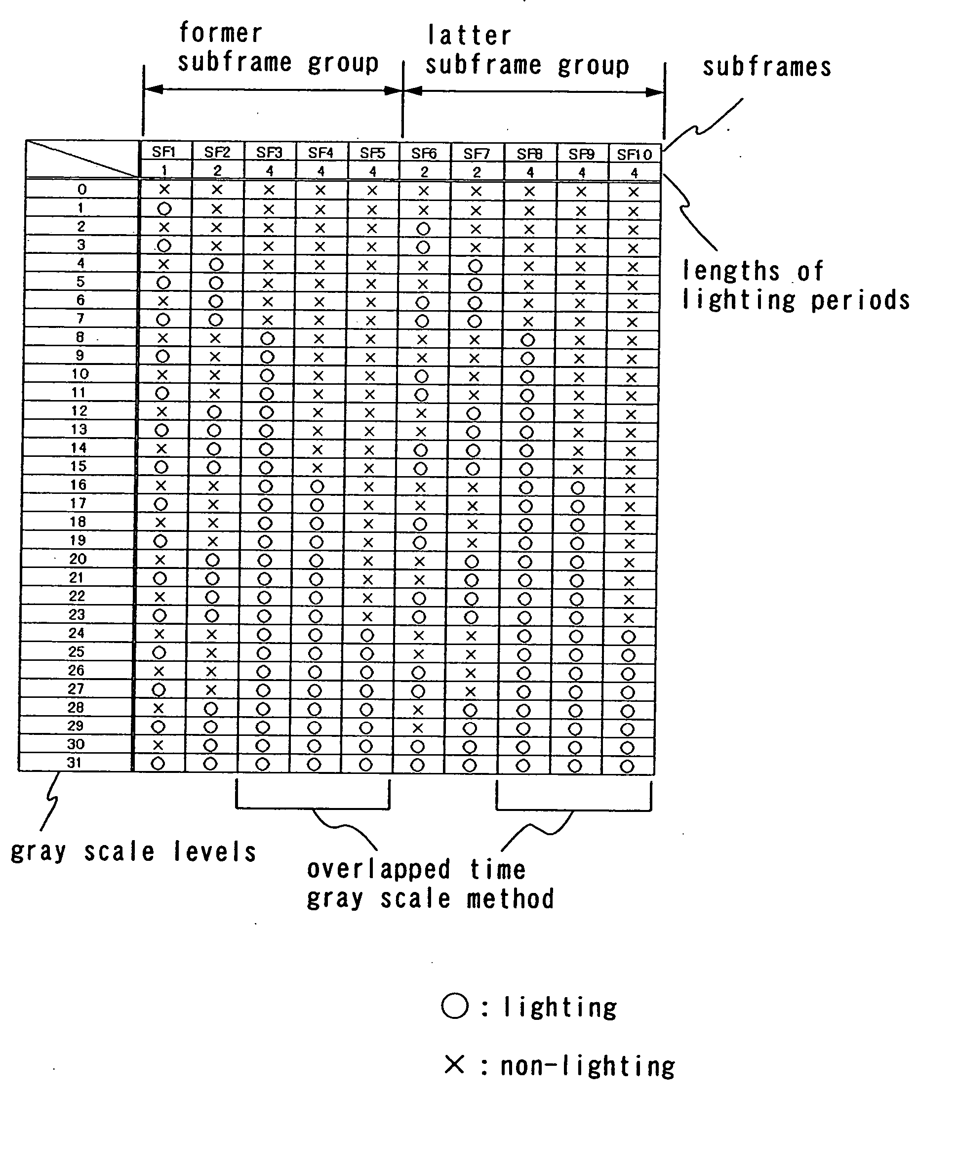
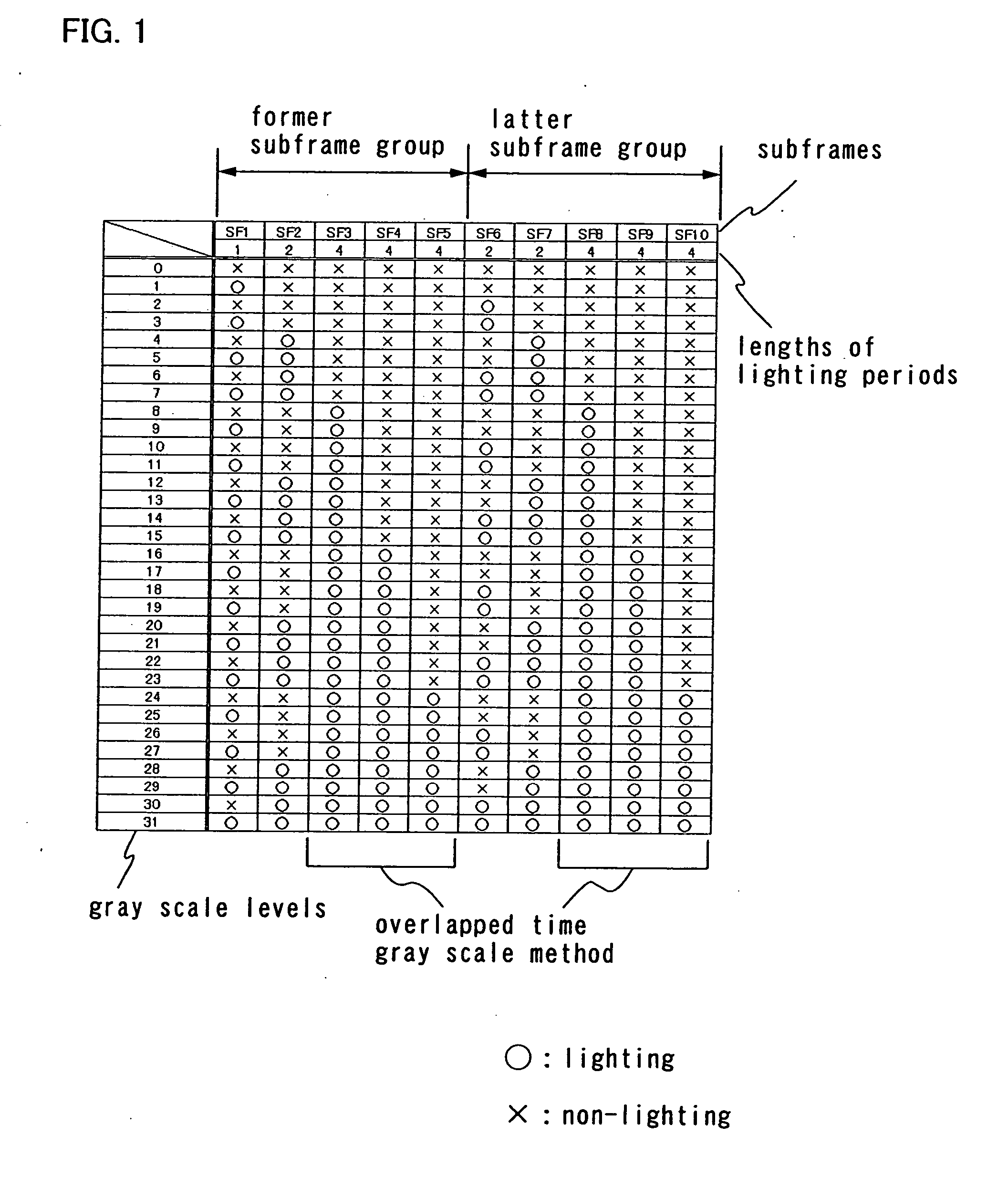
[0121] In the driving method of this embodiment mode, a conventional time gray scale method is used, and a subframe corresponding to bits belonging to a first bit group is divided into four, a subframe corresponding to bits belonging to a second bit group are divided into two, and a subframe corresponding to bits belonging to a third bit group is not divided. One frame is divided into a first subframe group and a second subframe group, and the four divided bits belonging to the first bit group are arranged in the respective subframe groups two by two. In addition, the two divided bits belonging to the second bit group are arranged in the respective subframes one by one, while the bits belonging to the third group are arranged in either one or both ...

embodiment mode 2

[0214] In Embodiment Mode 1, description is made on the case where one frame is divided into two subframe groups. However, the driving method of the invention enables one frame to be divided into three or more subframe groups. Therefore, this embodiment mode illustrates an example where one frame is divided into three or more subframe groups. Note that the number of subframes is not limited to 2 or 3, and may be appropriately determined.

[0215] In the exemplary driving method of this embodiment mode, which uses a conventional time gray scale method, a subframe corresponding to bits belonging to the first bit group is divided into six, a subframe corresponding to bits belonging to the second bit group is divided into three, and a subframe corresponding to bits belonging to the third bit group is not divided. Then, one frame is divided into three subframe groups. The six divided bits belonging to the first bit group are arranged in the three subframe groups two by two, the three divid...

embodiment mode 3

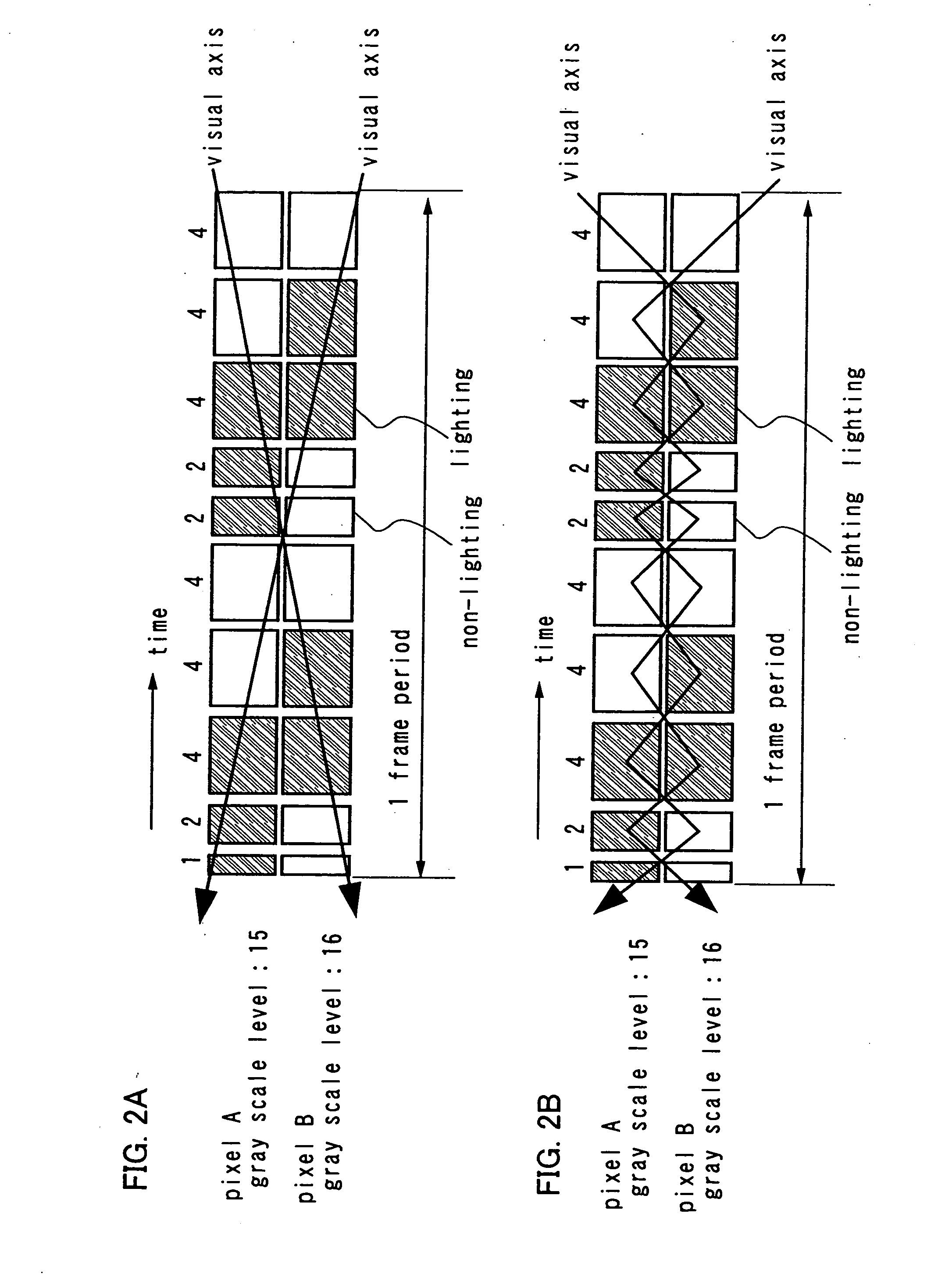
[0232] In this embodiment mode, description is made on an exemplary timing chart. In this specification, timing chart means a time-series chart which shows the selection state of pixels in one frame period. Although the selection method of subframes in FIG. 1 is used as an example here, the invention is not limited to this. Thus, the invention can be easily applied to other selection methods of subframes, the other number of gray scales, and the like.

[0233] In addition, although the subframes are arranged in order from SF1, SF2, SF3, SF4, SF5, SF6, SF7, SF8, FS9, and SF10 as an example, the invention is not limited to this and can be applied to other arranging order as well.

[0234] In the timing chart, the horizontal axis indicates the time, and time passes in the right direction. In addition, the vertical axis indicates the row number of pixels which are arranged in matrix. In this embodiment mode, pixels in one row are addressed (“to address” means to write a luminance signal int...


PUM


Abstract

The present invention provides a driving method of a display device for expressing gray scales with n bits (n is an integer) by dividing one frame into a plurality of subframes. By this driving method, pseudo contours which occur in displaying images by a time gray scale method can be reduced.

Description

BACKGROUND OF THE INVENTION [0001] 1. Field of the Invention [0002] The present invention relates to a display device and a driving method thereof. In particular, the invention relates to a display device using a time gray scale method. [0003] 2. Description of the Related Art [0004] In recent years, a so-called self-luminous display device is attracting attention, which has pixels each formed with a light-emitting element such as a light-emitting diode (LED). As a light-emitting element used in such a self-luminous display device, there is an organic light-emitting diode (also called an OLED (Organic Light-Emitting Diode), an organic EL element, an electroluminescence (EL) element, or the like), which has been attracting attention and used for an EL display or the like. Since the light-emitting element such as an OLED is a self-luminous type, it is advantageous as compared to a liquid crystal display in that high visibility of pixels is ensured, no backlight is required, high respo...

Claims


Application Information

Patent Timeline
Patent Type & Authority Applications(United States)
IPC IPC(8): G09G3/10H05B44/00
CPCG09G3/2022G09G3/2033G09G3/204G09G3/2077G09G3/3258H01L27/3265G09G2300/0809G09G2300/0842G09G2320/0261G09G2320/0266G09G2320/0276G09G2300/0426H10K59/1216G09G3/30G09G3/20H05B33/00
Inventor SHISHIDO, HIDEAKIKIMURA, HAJIMEYAMAZAKI, SHUNPEIKOYAMA, JUN
Owner SEMICON ENERGY LAB CO LTD
Why Eureka
Try Eureka