Polarized light source device and back light module for liquid crystal display

a back light module and liquid crystal display technology, applied in non-linear optics, lighting and heating apparatus, instruments, etc., can solve the problems of increasing the cost of the liquid crystal display, and achieve the effect of increasing the power efficiency, minimizing the light absorbed, and not lowering the energy efficiency

Inactive Publication Date: 2006-11-23
HANNSTAR DISPLAY CORPORATION
View PDF8 Cites 0 Cited by
  • Summary
  • Abstract
  • Description
  • Claims
  • Application Information

AI Technical Summary

Benefits of technology

[0017] It is an object of the present invention to provide a polarized light source for providing the liquid crystal display with the polarized light so as to increase the energy efficiency of the liquid crystal display.
[0018] It is another object of the present invention to provide a back light module for providing the liquid crystal display with the polarized light so as to increase the energy efficiency of the liquid crystal display.
[0022] Accordingly, the back light module or the polarized light source according to the present invention includes a polarizing element and thus provides the polarized light without lowering the energy efficiency. Also, the polarized light may be transmitted through the polarizing film of the liquid crystal display to minimize the light absorbed by the polarizing film. Therefore, the back light module or the panel light source according to the present invention dispenses with the expensive optical film and still meets the requirements of increasing the entire power efficiency, increasing the brightness, and lowering the cost of the liquid crystal display.

Problems solved by technology

Further, the cost of the liquid crystal display will increase more and more as the dimension of the liquid crystal display increases in recent years.

Method used


Image

  • Polarized light source device and back light module for liquid crystal display
  • Polarized light source device and back light module for liquid crystal display
  • Polarized light source device and back light module for liquid crystal display

Examples


Embodiment Construction

[0040] Referring to FIG. 6, it depicts a polarized light source device 100 according to an embodiment of the present invention. The polarized light source device 100 comprises a light source, such as a lamp 150, a reflector 161 surrounding the lamp 150, and a polarizer 192. The lamp 150 can be a cold cathode fluorescent lamp (CCFL).

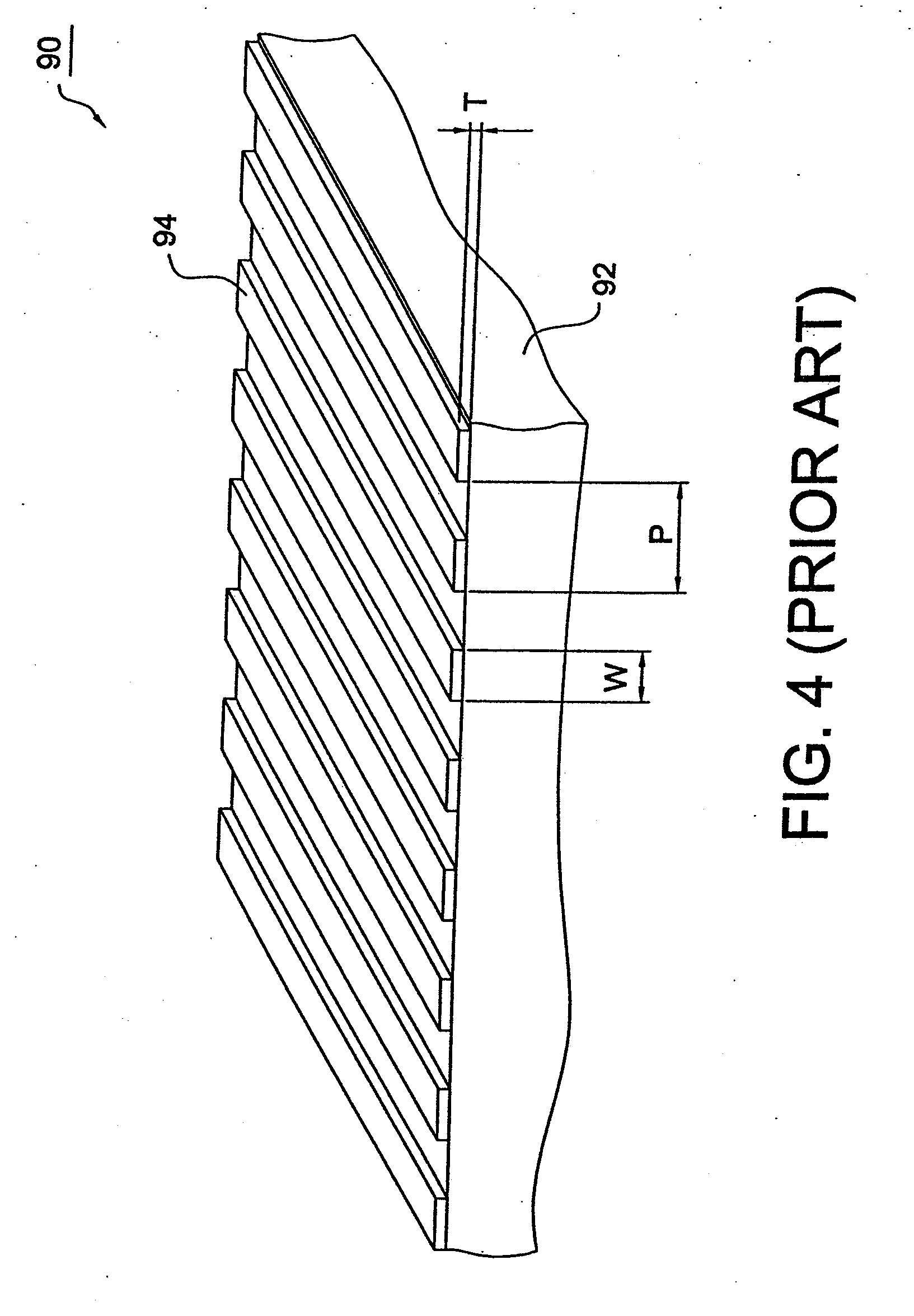
[0041] Now referring to FIG. 8, it depicts the polarizer 192 of the polarized light source device 100. The polarizer 192 comprises a transparent substrate 194, an antireflection layer 191 disposed on the transparent substrate 194, and metal grid wires 190 disposed on the antireflection layer 191. Light emitted from the lamp 150 is transmitted into the transparent substrate 194, through the antireflection layer 191, and out of the metal grid wires 190. The transparent substrate 194 is made of transparent material, such as glass and acrylic resin (PMMA), the refractive index of which is ns. The antireflection layer 191 is made of transparent dielectric mat...


PUM


Abstract

A polarized light source, has an illuminant for generating light having a transparent tube which is filled with mercury vapor and which has a fluorescent material disposed thereon; a reflective film surrounding the illuminant and having an opening for emitting the light; and a plurality of metal grid wires disposed at the opening for transmitting the light with a predetermined polarization therethrough; wherein the reflective film and the metal grid wires are disposed on the transparent tube.

Description

CROSS REFERENCE TO RELATED APPLICATION [0001] This application is a continuation of U.S. patent application Ser. No. 10 / 446,663 filed on May 29, 2003 in the name of Chen et al. which stands in condition for allowance. This application claims the priority benefit the above mentioned U.S. patent application Ser. No. 10 / 446,663 and of Taiwan patent application serial No. 091125380, filed Oct. 23, 2002 and Taiwan patent application serial No. 091136762, filed Dec. 16, 2002, the disclosures of which are hereby incorporated in their entirety by reference thereto.BACKGROUND OF THE INVENTION [0002] 1. Field of the Invention [0003] The present invention generally relates to a polarized light source device, and more particularly, to a back light module for a liquid crystal display (LCD) which provides polarized light with high transmittance. [0004] 2. Description of the Related Art [0005] Referring to FIG. 1, it depicts the structure of a conventional liquid crystal display. Generally, the li...

Claims


Application Information

Patent Timeline
Patent Type & Authority Applications(United States)
IPC IPC(8): F21V9/14H01J61/40F21V8/00G02B6/00
CPCG02B6/0023G02B6/0036G02B6/0043G02F2201/38G02F1/133604G02F1/13362G02F2001/133548G02B6/0056G02F1/133548
Inventor CHEN, WEI CHOUYANG, KEI HSIUNG
Owner HANNSTAR DISPLAY CORPORATION
Why Eureka
Try Eureka