Handheld device having ultrasonic transducer for axial transmission of acoustic signals

a transducer and axial transmission technology, applied in the field of ultrasonic transducers, can solve the problems of additional problems for both users, signal detection/transmission circuitry, and transmission of false information

Inactive Publication Date: 2006-12-07
MEASUREMENT SPEC
View PDF24 Cites 20 Cited by
  • Summary
  • Abstract
  • Description
  • Claims
  • Application Information

AI Technical Summary

Problems solved by technology

When the position of the pen tip is fixed on a point of the writing surface and the angle of pen is varied, the effective position of the cylindrical transducer moves, and false information is transmitted because the system is designed to detect the absolute position of the transducer.
Moreover, such transducers have been typically mounted externally on the pen, which causes additional problems for both the user, who must hold the stylus, and for the signal detection / transmission circuitry.
Structures disposed about the outer surface of the stylus in a ring-like manner and placement of the structure at or substantially near the location of the stylus tip interferes with the user's ability to adequately grasp or hold the stylus.
In addition, such location operates as an obstruction to the user's viewing of the information as it is being written.

Method used


Image

  • Handheld device having ultrasonic transducer for axial transmission of acoustic signals
  • Handheld device having ultrasonic transducer for axial transmission of acoustic signals
  • Handheld device having ultrasonic transducer for axial transmission of acoustic signals

Examples


Embodiment Construction

[0076] An aspect of the invention comprises a cylindrical ultrasonic transducer structure having axial acoustic transmission characteristics. The cylindrical ultrasonic transducer structure of the invention is especially intended for use as an ultrasonic transmitter. However, one of ordinary skill in the art will appreciate that the cylindrical ultrasonic transducer structure of the invention may also be utilized as a receiver.

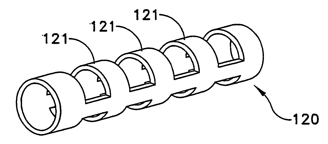
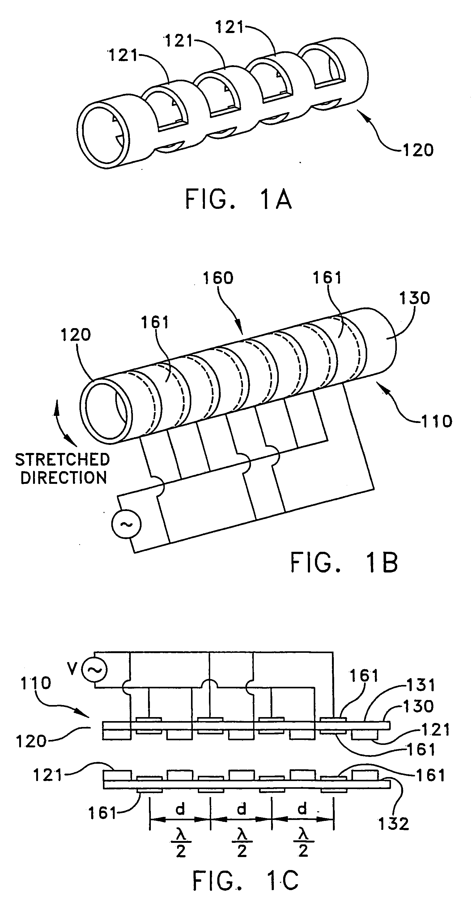
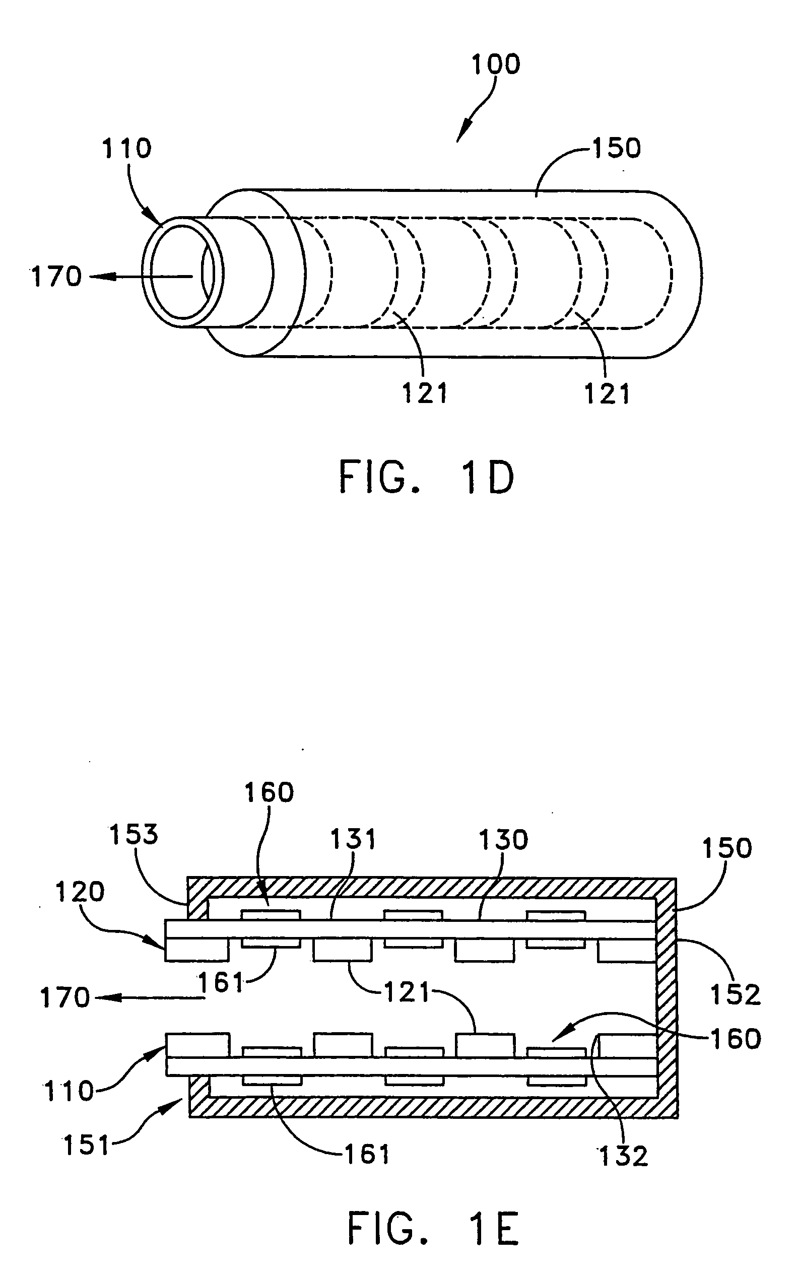
[0077] Referring now to FIGS. 1A-1E, and initially to FIG. 1E, there is shown an embodiment of a multi-segment, cylindrical ultrasonic transducer (MSCUT) structure 100 according to the invention. The MSCUT structure 100 generally comprises a multi-segment, cylindrical transducer 110 disposed within a cylindrical cover 150 having an open first end 151 and a closed second end 152. The transducer 110 is formed by a generally hollow mandrel or holder 120 having multiple cylindrical sections 121 (FIG. 1A), and a cylindrical piezoelectric transducer film 130 dispos...


PUM


Abstract

A handheld stylus having an elongated housing, a writing and drawing implement disposed within the housing and including a tip extending through an opening at an end of the housing where ultrasonic waves radiate therefrom and are used for determining a position of the stylus; and at least one ultrasonic transducer disposed within the housing. The transducer may be a cylindrical piezoelectric transducer having a holder and a cylindrical piezoelectric film spanning between at least two spaced apart cylindrical surfaces of the holder, or a flat transducer having a diaphragm, and a piezoelectric material disposed on a surface of the diaphragm.

Description

CLAIM FOR PRIORITY [0001] This application is a divisional application of co-pending U.S. patent application Ser. No. 10 / 625,482 filed Jul. 27, 2003, which claims the benefit under 35 U.S.C. 119(e) of U.S. Provisional Application Nos. 60 / 397,579, filed Jul. 22, 2002 and 60 / 453,322, filed Mar. 10, 2003.FIELD OF THE INVENTION [0002] The invention relates to ultrasonic transducers and more particularly to ultrasonic transducers used as transmitters and / or receivers in a handheld stylus device. BACKGROUND OF THE INVENTION [0003] Communications between an ultrasonic transducer mounted or positioned on a movable stylus (such as a moveable pen) and other remotely located transducers (for example, transducers fixed at remote positions from the stylus) make it possible to determine the position of the pen and ultimately to reproduce information associated with stylus movement. The digital information associated with the stylus position might be used for drawings, maps, or pictorial illustrat...

Claims


Application Information

Patent Timeline
Patent Type & Authority Applications(United States)
IPC IPC(8): H01L41/08A61B8/00B06B1/06H04R17/00G06F3/033H01L41/04H01L41/09H01L41/187H01L41/193H04B
CPCB06B1/0655G06F3/03545B06B1/0688A61B8/4209Y10S310/80A61B8/00
Inventor TODA, MINORU
Owner MEASUREMENT SPEC
Why Eureka
Try Eureka