Hypodermic syringe needle assembly

a syringe needle and hypodermic technology, applied in the field of hypodermic syringe needles, can solve the problems of unacceptable accidental injury risk, particularly dangerous, and the inability to readily substitute generic syringe barrels

Inactive Publication Date: 2006-12-14
MOHAMMED OWAIS
View PDF1 Cites 32 Cited by
  • Summary
  • Abstract
  • Description
  • Claims
  • Application Information

AI Technical Summary

Benefits of technology

[0014] Preferably, the tubular sheath or container features a tubular wall having a longitudinal slot therethrough. One end of the container is open so that a syringe barrel may be received therein. The second, or posterior, end of the container has an opening which is sufficiently large to allow a hypodermic needle to pass therethrough, but is too small to allow the hub or a syringe barrel to pass therethrough. A spring may engage the hub of the needle assembly and a ridge on the interior of the wall of the second end of the container. This spring biases the hub away from the second end of the container so that the needle attached to the hub is hidden within the container. When the spring is compressed, the needle is able to pass through the opening of the posterior end of the container. A pin attached to the annular sleeve is slidably engaged by the longitudinal slot in the container wall, holding the needle within the container while allowing it to slide back and forth. A knob mounted on the pin is positioned outside the container. The knob is too large to pass through the longitudinal slot, and acts to position the hub of the needle along the axis of the container. When the knob is pushed toward the second end of the container, the hub moves toward the second end of the container, compressing the spring and causing the needle to emerge through the second open end of the container. A means for reversibly engaging the knob when the spring is compressed is also provided. This allows the needle to be retained in an exposed position.

Problems solved by technology

However, there is an unacceptable risk of accidental injury resulting from contact with the point of the needle during the recapping step.
This is particularly dangerous as biological fluids contaminating the needle could enter the user's bloodstream.
The syringe barrel used with this assembly has a highly specialized structure, a generic syringe barrel cannot readily be substituted.
Also, the syringe barrel cannot readily be sterilized and reused.
Finally, there is the risk of accidentally squeezing the elliptical needle guard, causing the spring to move the needle guard into a position which conceals the needle prior to use of the needle.
However, this device causes the user to place his hand in proximity to the needle at the time it is exposed, increasing the likelihood of injury from accidental contact with the needle.
No mechanism for latching the sheath in a position which exposes the needle is provided, however.
This mav be an inconvenience for workers who wish to see the precise spot where they are administering an injection.
First, in a medical environment time is often a critical factor.
Most commonly used medical syringe barrels have frusto-conical tips which frictionally engage syringe needle hubs having frusto-conical cavities therein; such commonly used barrels cannot be used with the threaded connections envisioned by D'Amico.
Most commonly available syringe needle hubs have a single standard size, and cannot be used with a range of tubular cover sizes.
Also, since the diameter of D'Amico's hub is very nearly equal to the interior diameter of the tubular cover, it is difficult to insert a hub having a protruding pin into the cover.

Method used


Image

  • Hypodermic syringe needle assembly
  • Hypodermic syringe needle assembly
  • Hypodermic syringe needle assembly

Examples


Embodiment Construction

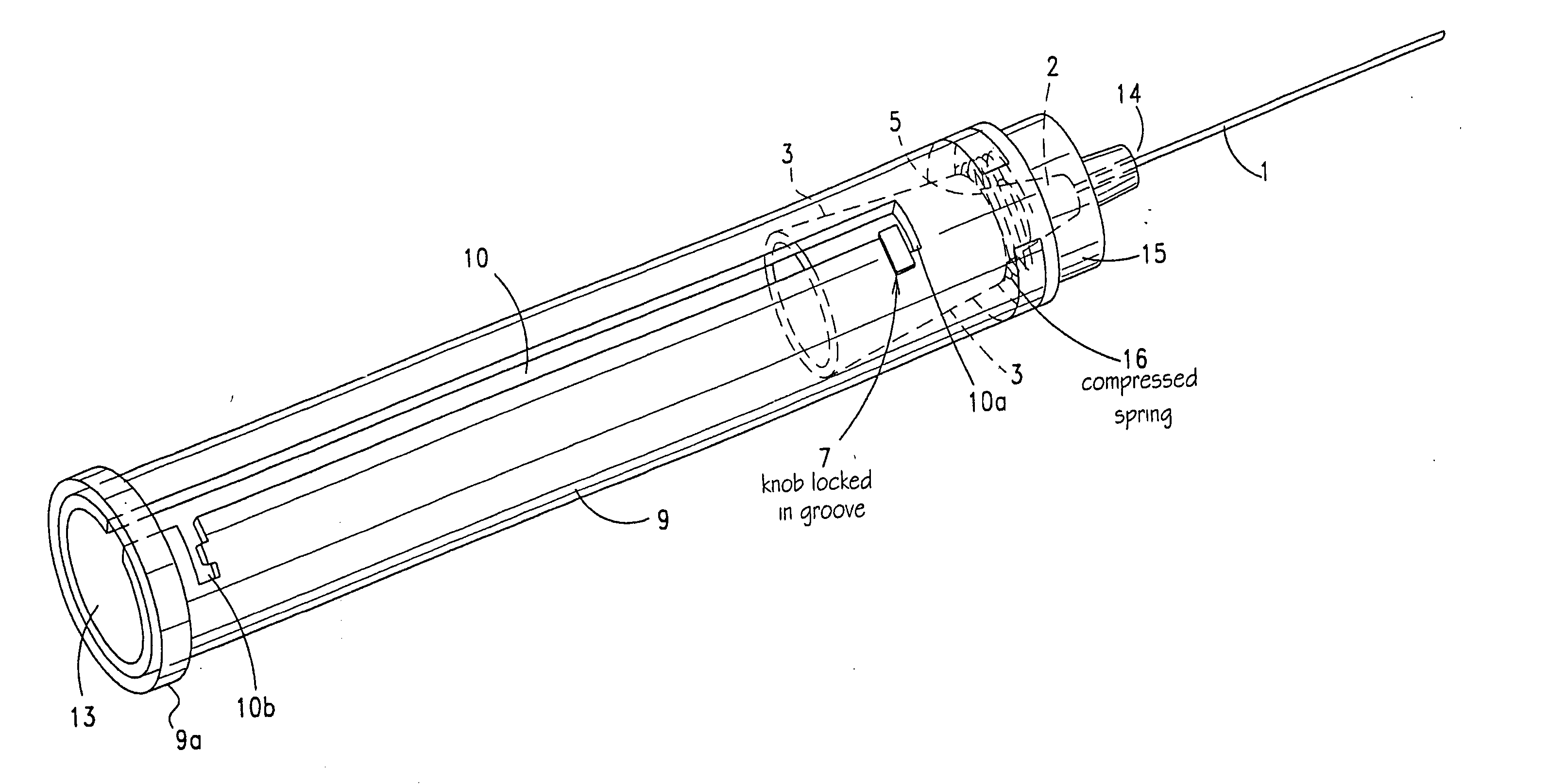
[0077] The needle used in the present invention is designed for use with a syringe comprising a plunger and a syringe barrel having a tubular wall with a defined outer diameter, where the barrel has an open end adapted to receive the plunger and a closed end having a cylindrically symmetric tip projecting therefrom. The tip of the barrel has a defined diameter which is less than the defined outer diameter of the syringe barrel and a longitudinal bore passing through the tip and the closed end of the barrel.

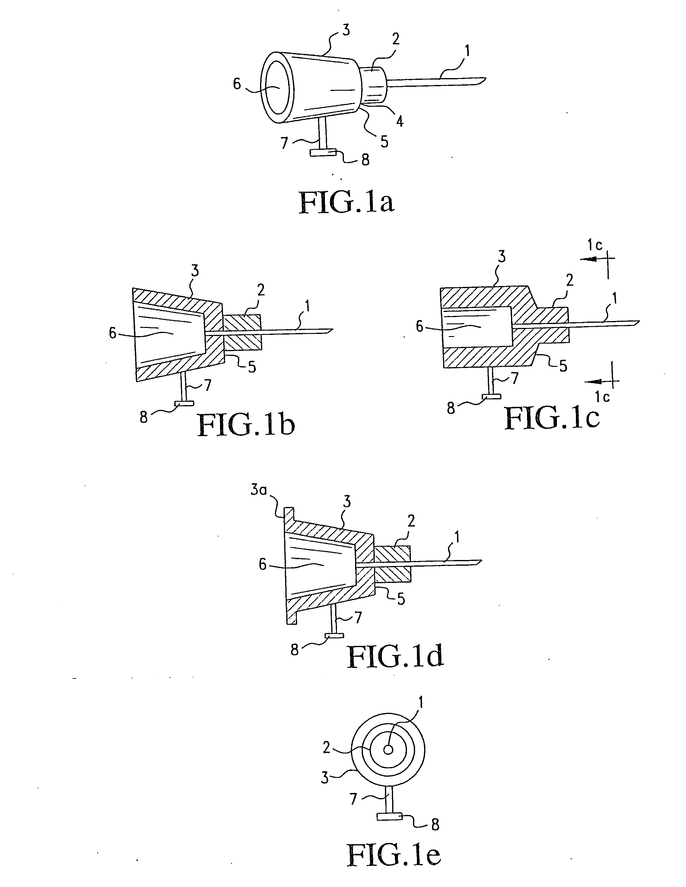
[0078]FIG. 1a illustrates a hypodermic needle for use in the syringe assembly of this invention. Needle 1 is affixed to hub 2. A hollow bore runs longitudinally through needle 1 and hub 2. An annular sleeve 3 is affixed to the outer periphery 4 of hub 2. A ledge 5 encircling hub 2 is defined by the edge of sleeve 3. Sleeve 3 defines a cavity 6 adapted to frictionally engage the tip of the syringe barrel, as shown in the cross-sectional views of FIGS. 1b and 1c. The diameter of ca...


PUM


Abstract

A combination of a retractable needle assembly and a syringe where the attachment of the retractable needle assembly and the syringe is the same regardless of the sizes of the retractable needle assembly and the syringe, resulting in a universal design

Description

REFERENCE TO RELATED APPLICATION [0001] This application is a continuation-in-part of Ser. No. 10 / 670,362, filed Sep. 26, 2003, which is a continuation-in-part of Ser. No. 10 / 157,885, filed May 31, 2002, which is continuation-in-part of Ser. No. 10 / 133,491, filed Apr. 29, 2002 which is a continuation in part of Ser. No. 09 / 613,753, filed Jul. 11, 2000, which is a continuation-in-part of Ser. No. 09 / 471,094, filed Dec. 23, 2999. The disclosure of the applications cited above is incorporated by reference herein. Additionally, the disclosure of each of the following applications having Owais Mohammad named as inventor is incorporated by reference herein: Ser. No. 09 / 218,040, filed Dec. 22, 1998; and Ser. No. 09 / 316,047, filed May 21, 1999.BACKGROUND OF THE INVENTION [0002] The present invention generally refers to hypodermic syringe needles for medical use. More particularly, the invention relates to hypodermic safety needles which retract into a container when not in use, preventing u...

Claims


Application Information

Patent Timeline
Patent Type & Authority Applications(United States)
IPC IPC(8): A61M5/32
CPCA61B5/1444A61M5/3232A61M2005/3253A61M2005/3228A61M5/3272A61B5/15003A61B5/150259A61B5/150389A61B5/150473A61B5/150503A61B5/150717A61B5/15074A61B5/153A61B5/154A61B5/150656
Inventor MOHAMMED, OWAIS
Owner MOHAMMED OWAIS
Why Eureka
Try Eureka