Structure of changing gas cylinder for air guns and paintball guns

Inactive Publication Date: 2006-12-28
WEI WILSON
View PDF22 Cites 11 Cited by
  • Summary
  • Abstract
  • Description
  • Claims
  • Application Information

AI Technical Summary

Benefits of technology

[0006] The primary objective of the present invention is to provide an improved structure of changing gas cylinder for air guns and paintball guns, which includes a bottle frame having a lateral through hole on a gun handles, a prop screwed at the bottom of the bottle frame and turned by hands to be moved vertically up and down, a valve installed at the top of the bottle frame and connected to a gas supply valve tube, and a track disposed along both sides of the handle and latched by an embedded member of a U-shape handle cover. After the U-shape handle cover is sheathed along the tracks and blocked by the bottom edge of the track, the bottle frame can be exposed without removing the U-shape handle cover. The prop can be screwed downward to unload or install the pressurized gas cylinder, or screwed upward to push the pressurized gas cylinder to move upward, such that the gas cylinder is combined with the valve and expedites the pressurized gas to be discharged from the valve for shooting. The U-shape handle cover can be pushed forward along the track to completely seal and cover the pressurized gas cylinder to form a handle for users to hold the gun without completely removing the prop or the U-shape handle cover to change the pressurized gas cylinder so as to give a quick, easy and convenient operation.
[0007] The secondary objective of the present invention is to provide an improved structure of changing gas cylinder for air guns and paintball guns, which extends the lower end of the U-shape handle cover such that when the U-shape handle cover slides forward along the track, a knob of the prop at the bottom of the bottle frame can be sealed and covered, so as to prevent it from being scratched and improve its artistic look.

Problems solved by technology

Since the displacement of the turning is longer when changing the pressurized gas cylinder, it is time-consuming and inconvenient.
However, the removed protective cover is separated from the gun handle, and the protective cover may be lost or missing easily, which also results in a time-consuming and inconvenient installation.

Method used


Image

  • Structure of changing gas cylinder for air guns and paintball guns
  • Structure of changing gas cylinder for air guns and paintball guns
  • Structure of changing gas cylinder for air guns and paintball guns

Examples


Embodiment Construction

[0013] To make it easier for our examiner to understand the present invention, the following detailed description with reference to the accompanying drawings of an embodiment are given for example, but such preferred embodiment is not intended to limit the scope of the present invention.

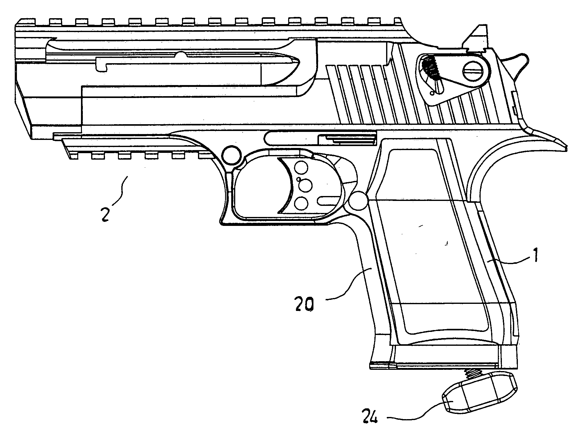
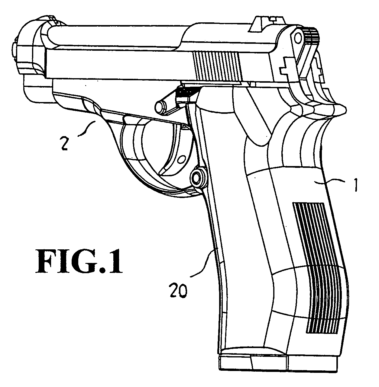
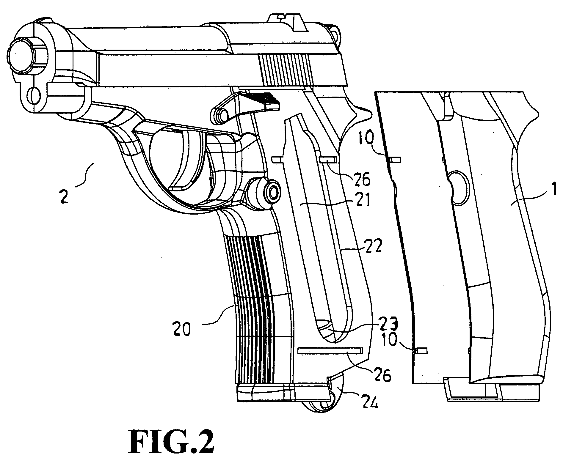
[0014] Referring to the figures, the improved structure of the present invention comprises a U-shape handle cover 1 and a gun 2; wherein the gun 2 forms a bottle frame 22 having a lateral through hole 21 at the handle 20, and a prop 23 is installed at the bottom of the bottle frame 22, and the prop 23 can be turned by a knob 24 to move vertically up and down, and a valve (not shown in the figure) is installed at the top of the bottle frame 22 and connected to a gas supply valve tube, and a track 26 is disposed from the front to the rear along both sides of the handle 20. The track 26 is latched by an embedded member 10 inside the U-shape handle cover 1, and the U-shape handle cover 1 is moved toward...


PUM


Abstract

An improved structure for changing gas cylinder for air guns and paintball guns includes a bottle frame having a lateral through hole on a gun handles, a prop screwed at the bottom of the bottle frame and turned by hands to be moved vertically up and down, a valve installed at the top of the bottle frame and connected to a gas supply valve tube, a track disposed along both sides of the handle and latched by an embedded member of a U-shape handle cover. After the U-shape handle cover is sheathed along the tracks and blocked by the bottom edge of the track, the bottle frame can be unloaded without removing the U-shape handle cover. The prop can be screwed downward to unload or install the pressurized gas cylinder, or screwed upward to push the pressurized gas cylinder to move upward, such that the gas cylinder is combined with the valve and expedites the pressurized gas to be discharged from the valve for shooting the gun. The U-shape handle cover can be pushed forward along the track to completely seal the pressurized gas cylinder to form a handle for users to hold the gun without completely removing the prop or the U-shape handle cover to change the pressurized gas cylinder so as to give a quick, easy and convenient operation.

Description

BACKGROUND OF THE INVENTION [0001] 1. Field of the Invention [0002] The present invention relates to an improved structure of changing gas cylinder for air guns and paintball guns, which is designed for solving the problems of a slow and inconvenient way of changing the gas cylinder for air guns and paintball guns. A handle of an air gun or a paintball gun forms a bottle frame with a lateral through hole, and a prop is installed at the bottom of the bottle frame, and the prop can be turned by hands to move vertically up and down. A valve connected to a gas supply valve tube is installed at the top of the prop, and a track running along both sides from the front to the rear of the handle, and the track is latched by an embedded member protruded from the interior of a U-shape handle cover, such that the U-shaped handle cover slides along the track to the rear end until it is stopped by the end of the track. It is not necessary to take out the U-shape handle cover to expose the bottle ...

Claims


Application Information

Patent Timeline
IPC IPC(8): F41B11/00
CPCF41B11/62
Inventor WEI, WILSON
Owner WEI WILSON
Why Eureka
Try Eureka