Heat sink retainer unit and thermal module device

Active Publication Date: 2015-10-15
ASIA VITAL COMPONENTS SHENZHEN CO LTD
View PDF12 Cites 6 Cited by
  • Summary
  • Abstract
  • Description
  • Claims
  • Application Information

AI Technical Summary

Benefits of technology

The present invention provides a heat sink retainer unit and a thermal module device that can be quickly installed or uninstalled without using any hand tool. The heat sink retainer unit includes an elastic member for applying elastic latching force to the heat sink, which makes the operation easier and keeps the heat sink in tight contact with a heat generation electronic component. The heat sink retainer unit can be easily and quickly operated in a limited space to latch or unlatch the heat sink, making the heat sink's installation and uninstallation faster and easier.

Problems solved by technology

In operation, the electronic components will generate a great amount of heat to lead to rise of temperature of the electronic components themselves and the entire system.
This will affect the stability of the system.
Therefore, it is hard to operate the heat sink retainer unit within a limited (narrowed) space to fix the heat sink.

Method used


Image

  • Heat sink retainer unit and thermal module device
  • Heat sink retainer unit and thermal module device
  • Heat sink retainer unit and thermal module device

Examples


Embodiment Construction

[0028]The embodiments of the present invention will be described hereinafter with reference to the drawings, wherein the same components are denoted with the same reference numerals.

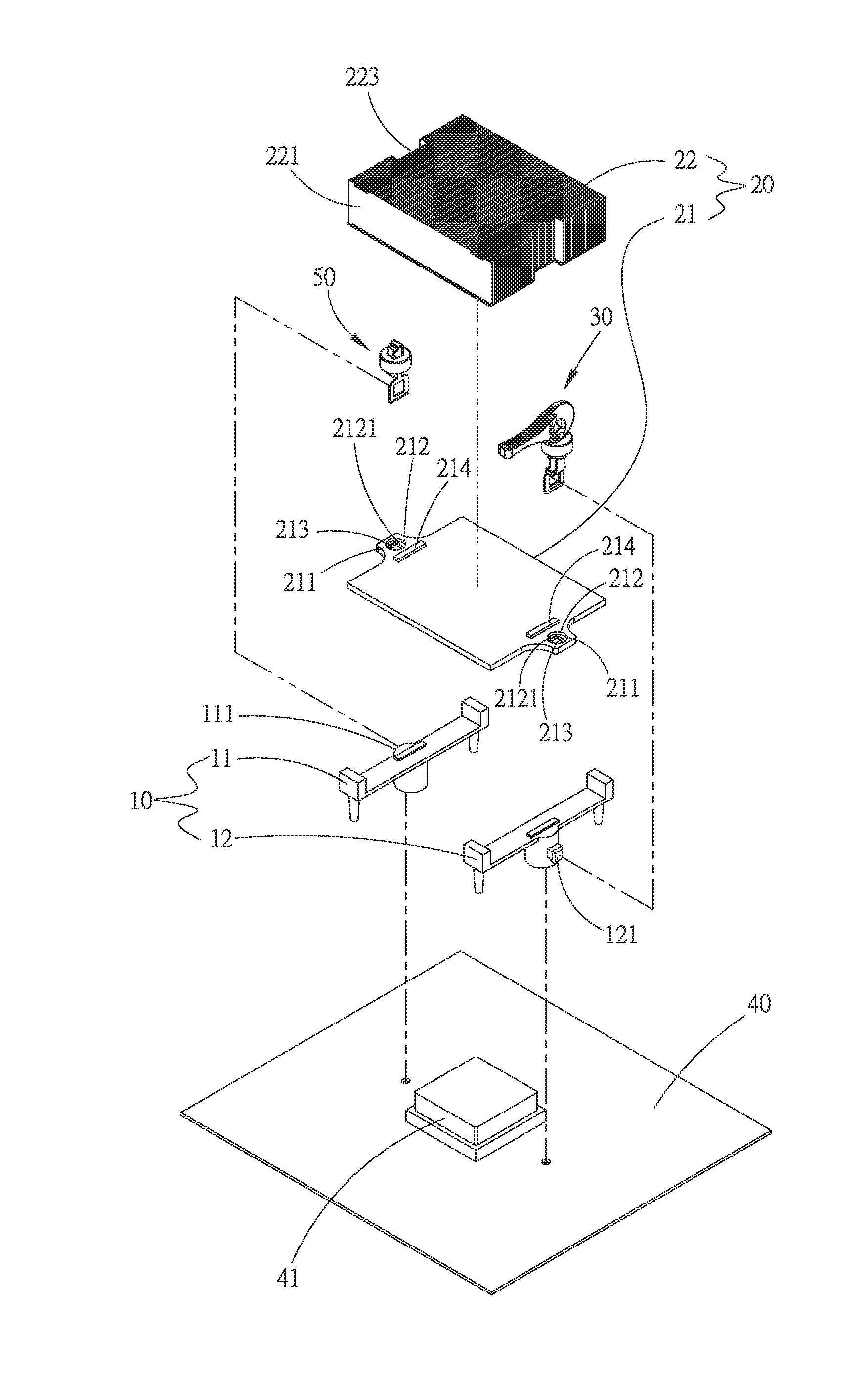
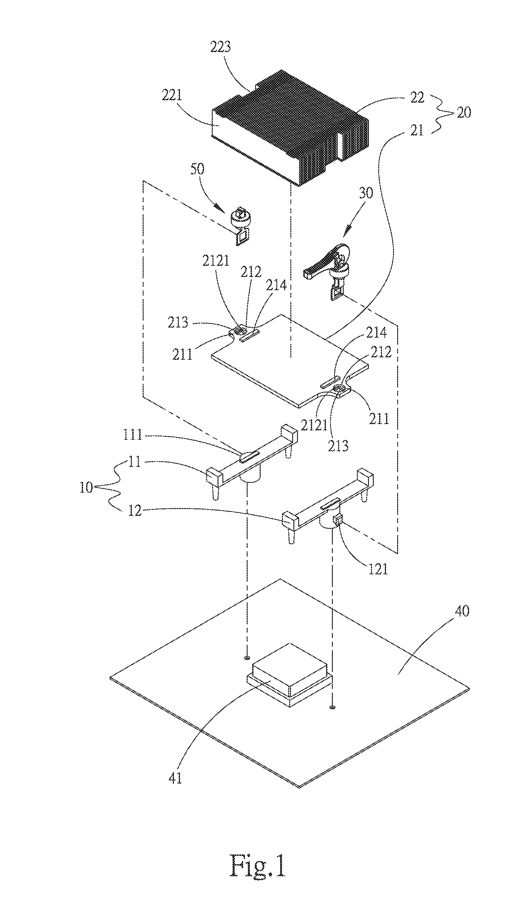
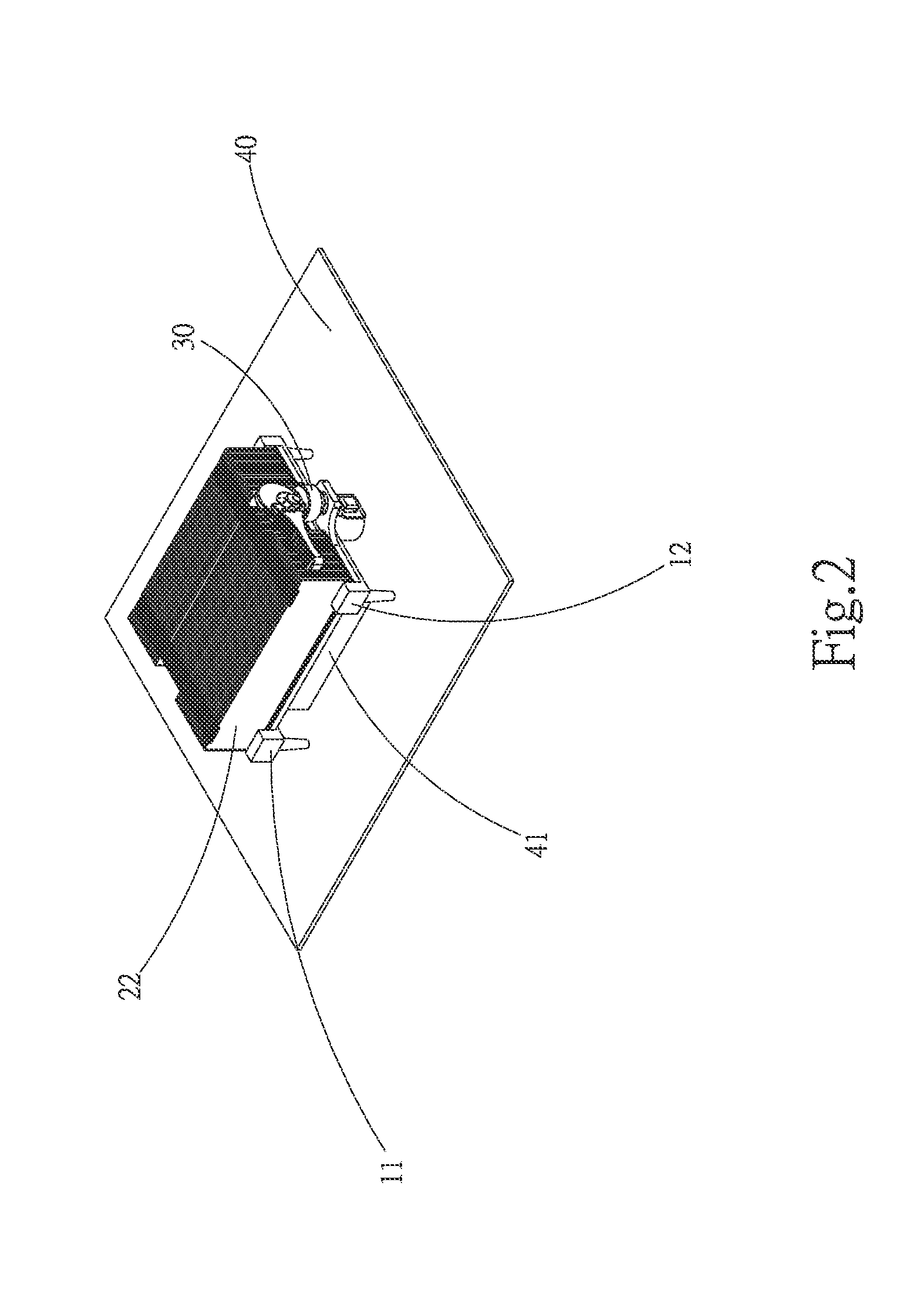
[0029]Please refer to FIGS. 1 and 2. FIG. 1 is a perspective exploded view of the thermal module device of the present invention. FIG. 2 is a perspective assembled view of the thermal module device of the present invention. The thermal module of the present invention includes a fixing seat 10, a heat sink 20 and a heat sink retainer unit 30. The fixing seat 10 is mountable on a circuit board 40. The heat sink 20 is attached to the surface of a heat generation electronic component 41 on the circuit board 40. The heat sink retainer unit 30 is disposed on at least one side of the heat sink 20. Another heat sink retainer unit 50 is disposed on the other side of the heat sink 20. The heat sink retainer unit 30 and the other heat sink retainer unit 50 are latched with the fixing seat 10 to make the heat sink 2...


PUM


Abstract

A heat sink retainer unit includes a buckle body, a retainer member, an elastic member and a handle. The elastic member is disposed in the buckle body and fitted on the retainer member. The retainer member is passed through the buckle body from a lower side thereof. A top end of the retainer member is positioned above the buckle body. The handle is positioned above the buckle body and pivotally connected with the top end of the retainer member. By means of operating the handle, the retainer member can be moved up and down, whereby the elastic member can apply elastic force to the buckle body.

Description

BACKGROUND OF THE INVENTION[0001]1. Field of the Invention[0002]The present invention relates generally to a heat sink retainer unit, and more particularly to a heat sink retainer unit for fixedly mounting a heat sink on an electronic component and a thermal module device employing the heat sink retainer unit.[0003]2. Description of the Related Art[0004]In recent years, along with the rapid development of electronic industries, the operation speed of the electronic components has been continuously enhanced. In operation, the electronic components will generate a great amount of heat to lead to rise of temperature of the electronic components themselves and the entire system. This will affect the stability of the system. In order to ensure normal operation of the electronic components, generally a heat dissipation device is mounted on the electronic components to dissipate the heat generated by the electronic components.[0005]Currently, in general, a heat sink is mounted on each heat...

Claims


Application Information

Patent Timeline
IPC IPC(8): H05K7/20
CPCH05K7/2039H01L23/4093H01L2924/0002H01L2924/00
Inventor LIN, SHENG-HUANG
Owner ASIA VITAL COMPONENTS SHENZHEN CO LTD
Why Eureka
Try Eureka