User interface mechanism to formulate complex query against an entity relationship model

a user interface and entity relationship technology, applied in relational databases, data processing applications, instruments, etc., can solve problems such as difficulty in forming complex queries, question or asking, and increased problems, and achieve quick and easy building of queries

Inactive Publication Date: 2007-01-04
MICROSOFT TECH LICENSING LLC
View PDF5 Cites 22 Cited by
  • Summary
  • Abstract
  • Description
  • Claims
  • Application Information

AI Technical Summary

Benefits of technology

[0006] A graphical user interface and method of use thereof that allows users to interact with an entity relationship model. The user interface includes zones that allow users to navigate among the entities, roles and fields to create queries that are run against the model. Clicking on an entity in the shows the available fields for the entity. Users can drag and drop entities and fields onto a design surface to quickly and easily build queries. Rules are applied when either an entity or a field is dropped onto the design surface based upon the item being dropped (either an entity or a field), the position of the drop and also the properties that are associated with the item.

Problems solved by technology

Another problem is that while building queries or asking questions against an ER model is difficult. there is a desire to maintain power and flexibility in the questions that may be asked.
With this flexibility comes complexity especially when trying to formulate queries or questions against this model.
The problem is magnified when the individual trying to formulate the query is not familiar with relational design.

Method used


Image

  • User interface mechanism to formulate complex query against an entity relationship model
  • User interface mechanism to formulate complex query against an entity relationship model
  • User interface mechanism to formulate complex query against an entity relationship model

Examples


Embodiment Construction

Exemplary Computing Environment

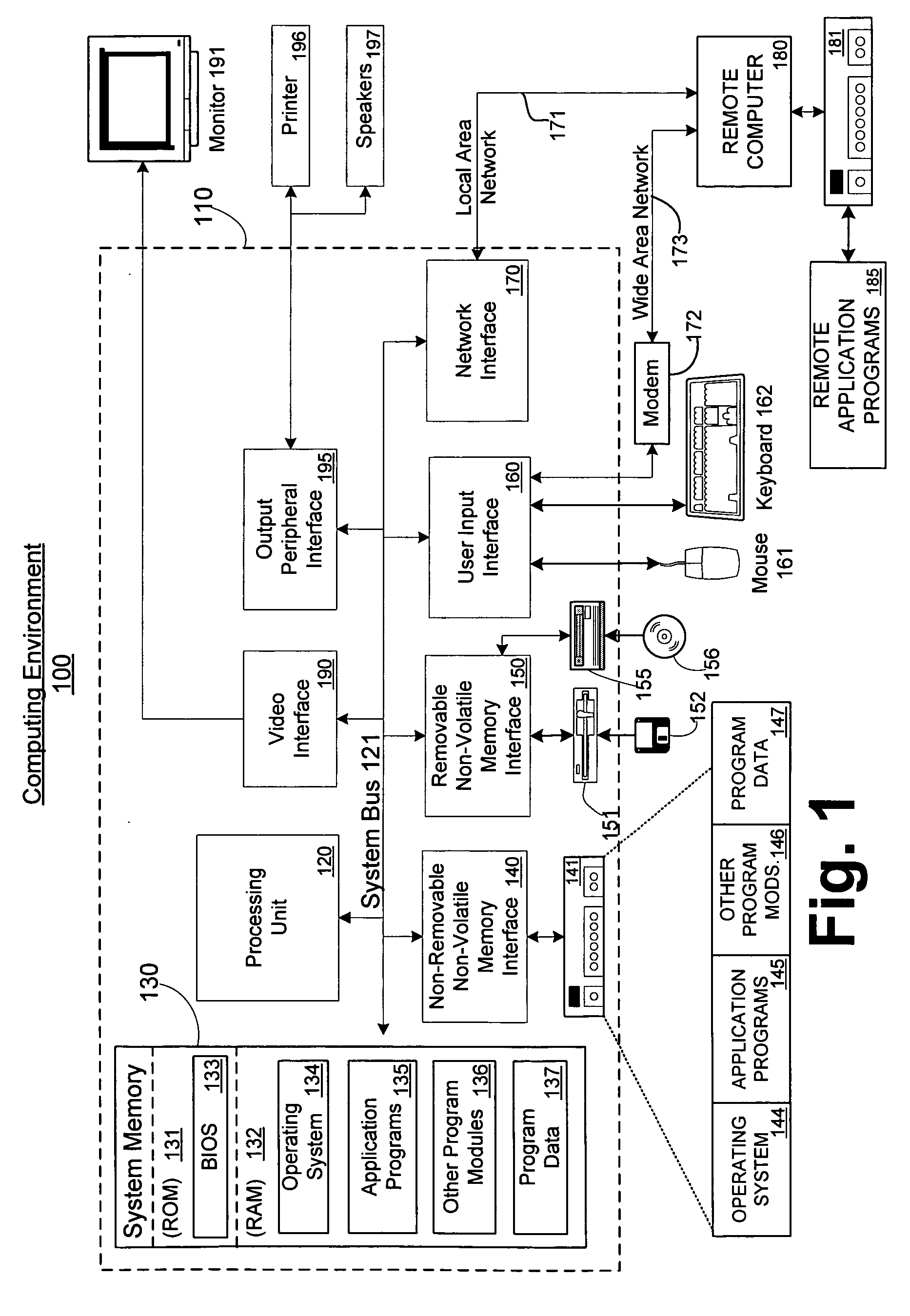
[0014]FIG. 1 illustrates an example of a suitable computing system environment 100 in which the invention may be implemented. The computing system environment 100 is only one example of a suitable computing environment and is not intended to suggest any limitation as to the scope of use or functionality of the invention. Neither should the computing environment 100 be interpreted as having any dependency or requirement relating to any one or combination of components illustrated in the exemplary operating environment 100.

[0015] The invention is operational with numerous other general purpose or special purpose computing system environments or configurations. Examples of well known computing systems, environments, and / or configurations that may be suitable for use with the invention include, but are not limited to, personal computers, server computers, hand-held or laptop devices, multiprocessor systems, microprocessor-based systems, set top boxes, pr...


PUM


Abstract

A graphical user interface and method of use thereof that allows users to interact with an entity relationship model. The user interface includes zones that allow users to navigate among the entities, roles and fields to create queries that are run against the model. Clicking on an entity in the shows the available fields for the entity. Users can drag and drop entities and fields onto a design surface to quickly and easily build queries. Rules are applied when either an entity or a field is dropped onto the design surface based upon the item being dropped (either an entity or a field), the position of the drop and also the properties that are associated with the item. Entities may be grouped and filtered to sort and limit the results of the query. After query is run, the results may be displayed in a separate area to the user.

Description

FIELD OF THE INVENTION [0001] This invention relates in general to the field of entity relationship modeling. More particularly, this invention relates to a user interface for formulating queries against an entity relationship model without requiring knowledge of entity relationships on the part of the user. BACKGROUND OF THE INVENTION [0002] An entity relationship (ER) diagram is a graphical representation of an organization's data storage requirements. Entity relationship diagrams are abstractions of the real world which simplify a problem to be solved while retaining its essential features. Entity relationship diagrams have three different components: entities, attributes and relationships. Entities are the people, places, things, events and concepts of interest. Entities may represent collections of things, for example, an employee entity might represent a collection of all the employees that work for an organization. Individual members (employees) of the collection are called o...

Claims


Application Information

Patent Timeline
Patent Type & Authority Applications(United States)
IPC IPC(8): G06F17/30
CPCG06F17/30604G06F16/288Y10S707/99943
Inventor CHAU, CAROLYN KHANHCARLSON, JASON DAVIDMEYERS, ROBERT ALANWELCKER, BRIAN LEEMUELLER, LISA RENEEMEYERS, AARON STEPHEN
Owner MICROSOFT TECH LICENSING LLC
Why Eureka
Try Eureka