Continuous web stress distribution measurement sensor

Inactive Publication Date: 2007-01-11
ARCONIC INC
View PDF24 Cites 28 Cited by
  • Summary
  • Abstract
  • Description
  • Claims
  • Application Information

AI Technical Summary

Benefits of technology

[0028] It is a further object of the invention to provide a method of measuring the stress distribution across a web of material passing across a roller, that is simpler and less

Problems solved by technology

Increasing the number of sensors provides more information about the stress di

Method used


Image

  • Continuous web stress distribution measurement sensor
  • Continuous web stress distribution measurement sensor
  • Continuous web stress distribution measurement sensor

Examples


Embodiment Construction

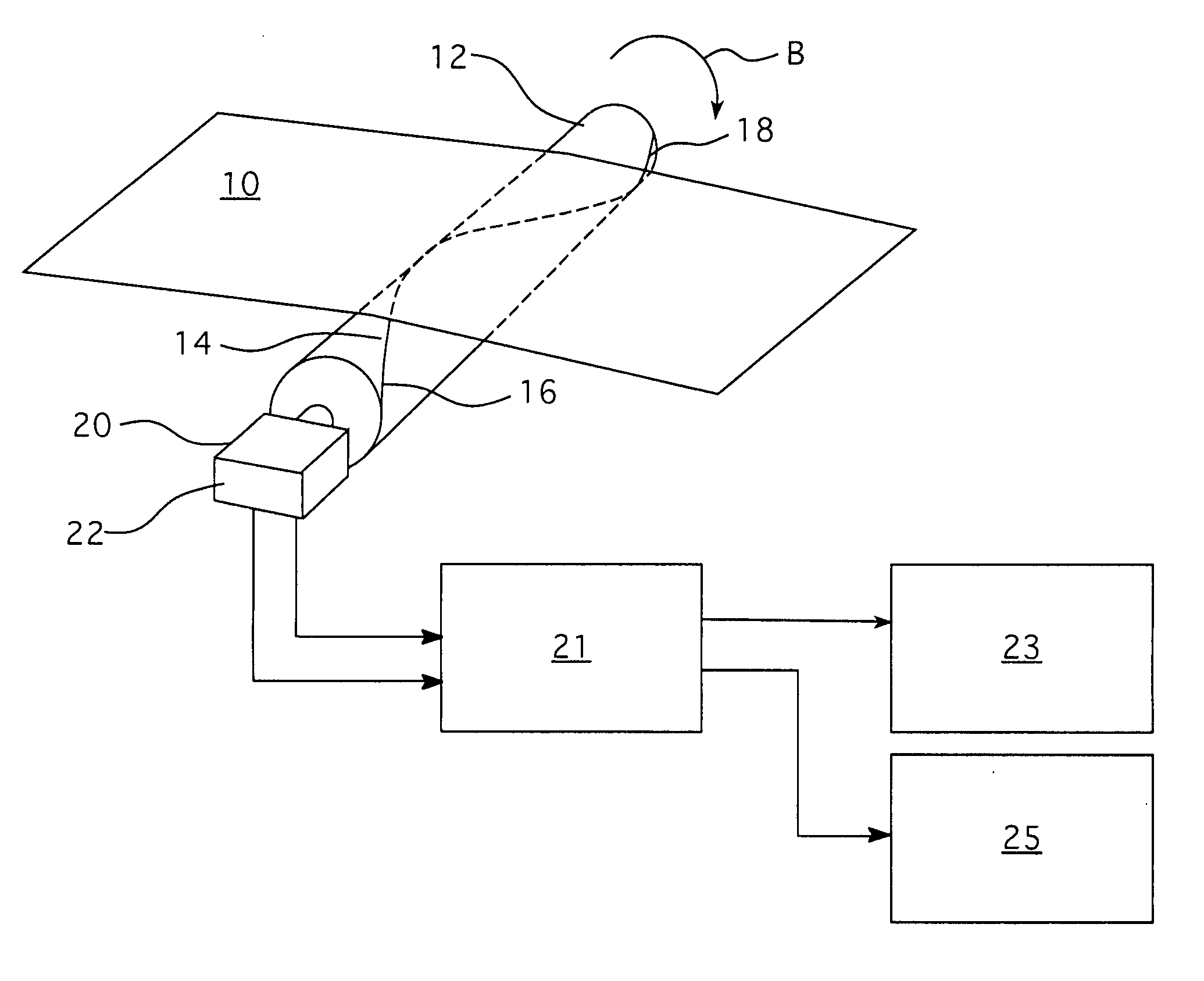
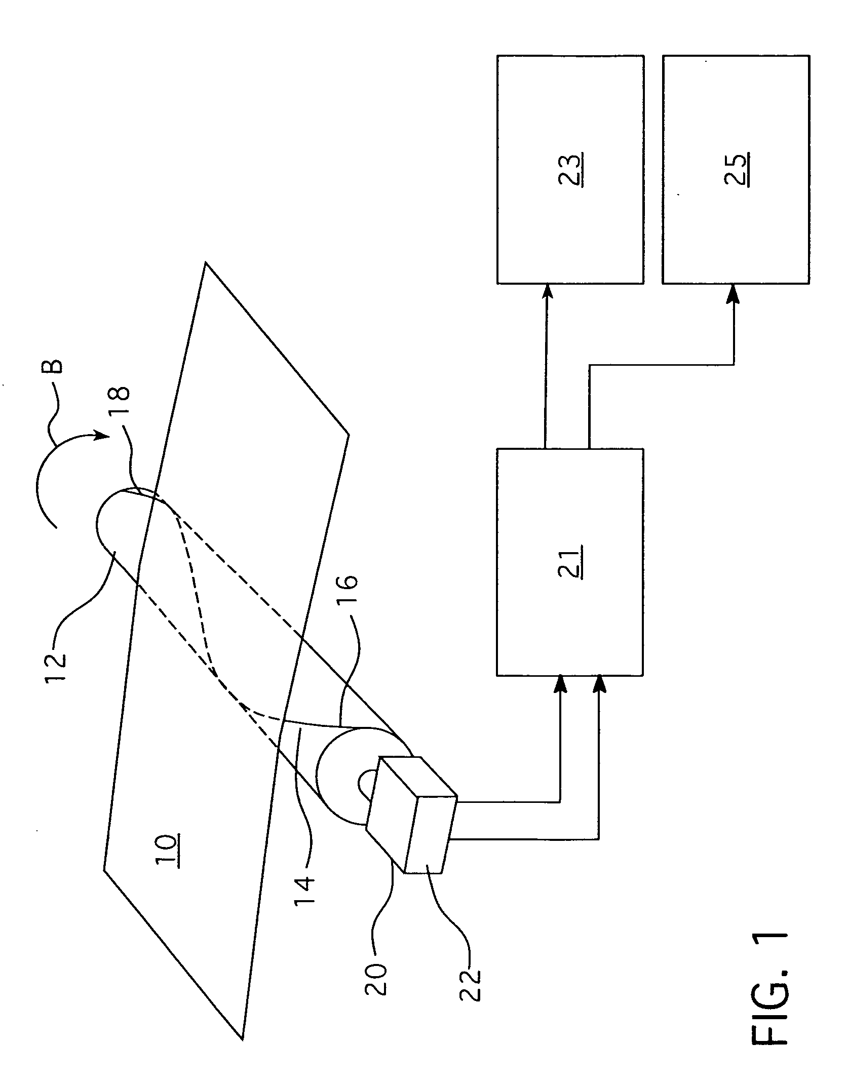
[0037] The present invention provides a continuous sensor wound in a helical pattern around a roller, for measuring the stress within a web of material passing over the roller.

[0038] Referring to FIG. 1, the web of material 10 passing over a roller 12 is illustrated. The roller 12 may be, for example, the last roller of a rolling mill. The roller 12 includes a sensor 14 wound in a helical pattern around the roller 12. The sensor 14 includes a pair of ends 16, 18. The sensor 14 is preferably wrapped around the roller 12 so that, as the material 10 passes over the roller, it applies pressure at one point on the sensor, with the point at which pressure is applied moving from one end of the roller to the other. As the material 10 stops applying pressure at the end 18 of the sensor 14, it begins applying pressure at the end 16 of the sensor 14.

[0039] In the embodiment of FIG. 1, the sensor 14 is a fluid filled tube having a pressure sensor 20 at the end 16. The tube may be made from an...


PUM


Abstract

A pressure sensor is wound in a helical pattern around a roller for providing a continuous measurement of the stress distribution within a material passing over the roller. The sensor may be a fluid filled tube having a pressure sensor at one end, or may be a piezoelectric ribbon. As the material passes over the roller, it is always applying pressure to one portion of the sensor. By monitoring the angular position of the roller, the points at which stress is being measured across the width of the material is known. The stress distribution may then be used to determine the flatness of the material passing over the roller.

Description

BACKGROUND OF THE INVENTION [0001] 1. Field of the Invention [0002] The present invention relates to measurements of the stress applied by a web of material passing over a roller. More specifically, the invention provides an apparatus and method for providing a substantially continuous measurement of the stress applied to various portions of the material across the roller, while determining where across the width of the web of material the stress is being applied. [0003] 2. Description of the Related Art [0004] When forming materials such as metal into sheets, for example, within a rolling mill, the flatness of the resulting material must be monitored. Various systems for monitoring this flatness, possibly through the tension the material applies to the last roller at the exit of the rolling mill, have been proposed. [0005] For example, U.S. Pat. No. 2,189,609, issued to G. P. Lessmann on Feb. 6, 1940, discloses a fluid-pressure operated tensionmeter for maintaining a predetermined ...

Claims


Application Information

Patent Timeline
IPC IPC(8): G01L5/04
CPCG01L5/045
Inventor SCHULTHEIS, FRED J.
Owner ARCONIC INC
Why Eureka
Try Eureka