Film forming apparatus

a film and film technology, applied in the direction of chemical vapor deposition coating, metal material coating process, coating, etc., can solve the problems of difficult fine patterning and uneven thickness of films, and achieve the effect of reducing uneven thickness

Inactive Publication Date: 2007-01-18
SEIKO EPSON CORP
View PDF5 Cites 12 Cited by
  • Summary
  • Abstract
  • Description
  • Claims
  • Application Information

AI Technical Summary

Benefits of technology

[0012] Also, by forming a plurality of films by discharging the same chemical species with at least two nozzles out of the plurality of nozzles, it is possible to form the plurality of films so as to each have a uniform thickness and quality as variations in orifice diameter, amount of discharge, etc., between the nozzles are thus equalized.
[0018] In the above-described film forming apparatus, the at least one nozzle may be capable of carrying out discharge in their respective positions that result from setting a plurality of relative positions between the at least one nozzle and the stage. In this case, it is possible to fix the distance between the nozzle and an area where a film is formed. Therefore, it is possible to reduce unevenness in thickness between portions of a film or set the thickness of each of a plurality of films at a predetermined value.

Problems solved by technology

Meanwhile, in an apparatus that employs the inkjet process, nozzles need be provided with a piezoelectric element, resulting in the necessity to provide a large nozzle pitch, making fine patterning difficult.
In addition, since the thickness of films changes with distance from an evaporation source, there is also a problem in uniformity in the thickness of the films.

Method used


Image

  • Film forming apparatus
  • Film forming apparatus
  • Film forming apparatus

Examples


first embodiment

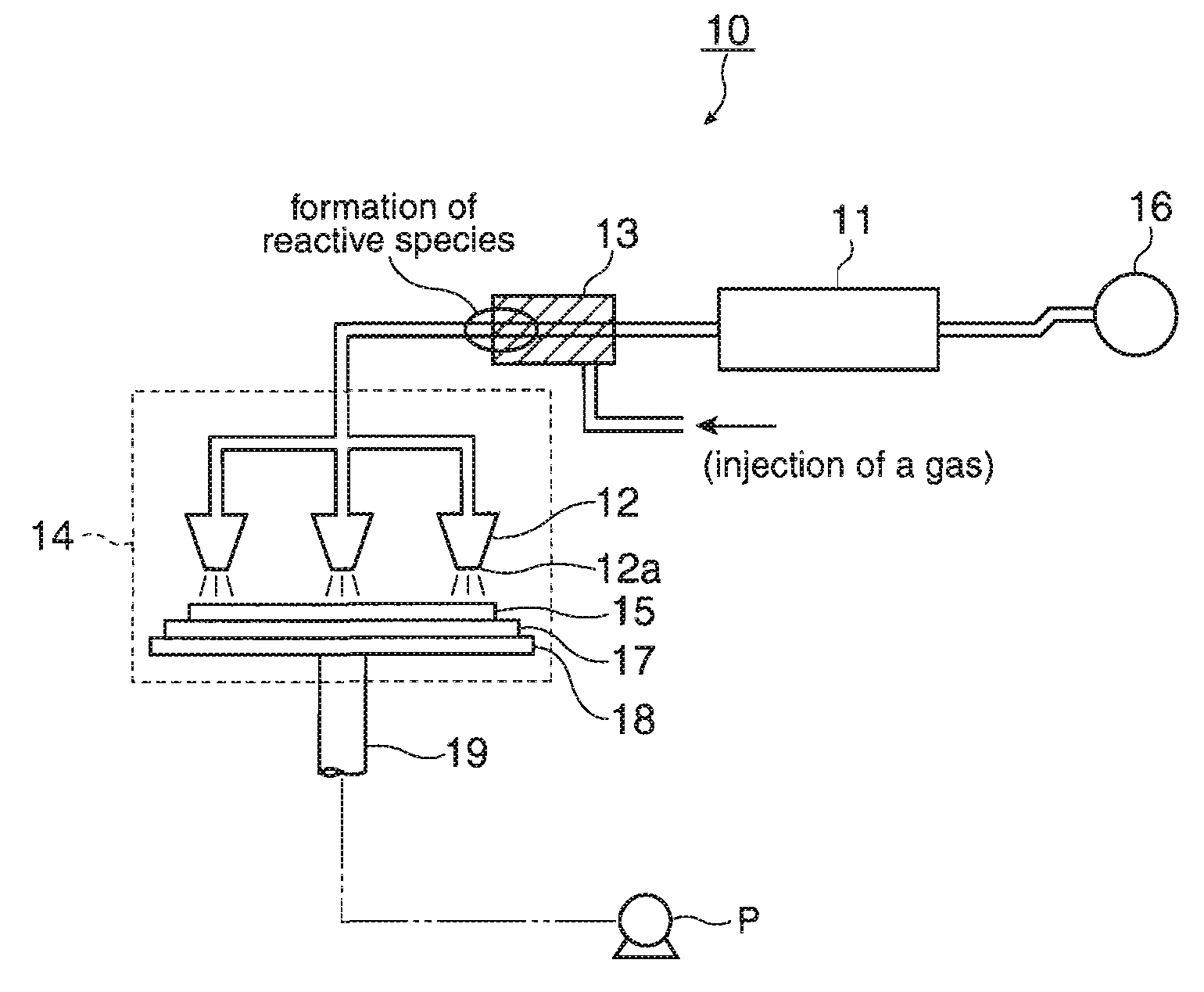
[0035]FIG. 1 is a schematic diagram illustrating a structure of a first embodiment of the film forming apparatus according to the invention.

[0036] In FIG. 1, a film forming apparatus 10 according to the first embodiment includes a material reservoir 11 for retaining a material and a plurality of nozzles 12, provided downstream of the material reservoir 11 via a flow channel, for carrying out a discharge to form a film. In addition, between the material reservoir 11 and the plurality of nozzles 12 is provided a heating section 13 that functions as a chemical species generation section for generating a chemical species, such as a reactive species or the like, with the aforementioned material as a precursor.

[0037] In addition, the film forming apparatus 10 further includes a chamber 14 that is configured to have arranged therein the plurality of nozzles 12, a substrate 15, on which a film is to be formed of the chemical species discharged from the nozzles 12, and a substrate stage 17...

second embodiment

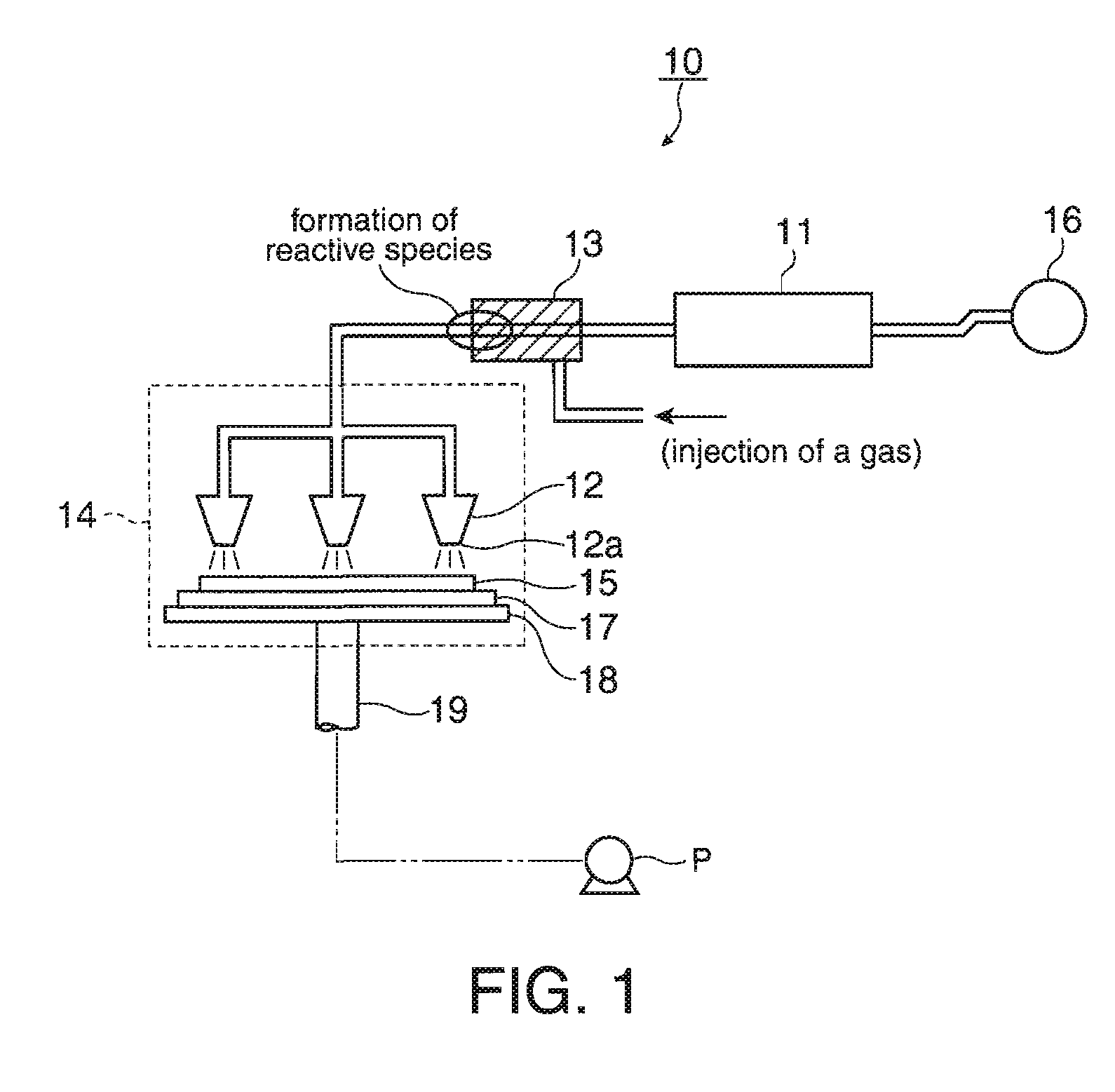
[0056]FIG. 2 is a schematic diagram illustrating a structure of a second embodiment of the film forming apparatus according to the invention.

[0057] In FIG. 2, a film forming apparatus 20 according to the second embodiment includes a material reservoir 21 for retaining a predetermined material and a plurality of nozzles 22, provided downstream of the material reservoir 21 via a flow channel, for carrying out a discharge to form a film. In addition, between the material reservoir 21 and the plurality of nozzles 22 is provided an optical window 23 that functions as a chemical species generation section for generating a chemical species, such as a reactive species or the like, with the aforementioned material as a precursor. Note that in this film forming apparatus 20, a light that is capable of generating the chemical species at the chemical species generation section may be introduced using an optical fiber or the like without using the optical window 23.

[0058] The film forming appa...

third embodiment

[0068]FIG. 3 is a schematic diagram illustrating a structure of a third embodiment of the film forming apparatus according to the invention.

[0069] In FIG. 3, a film forming apparatus 30 according to the third embodiment includes a material reservoir 31 for retaining a predetermined material, a plurality of nozzles 32, provided downstream of the material reservoir 31 via a flow channel, for discharging the material, and a substrate 35 on which a film is to be formed by discharging of the plurality of nozzles 32. The film forming apparatus 30 further includes an optical window 33 that functions as a means of chemical species generation for generating a chemical species, such as a reactive species or the like, with the material as a precursor when the plurality of nozzles 32 have discharged the material onto the substrate 35. Note that in this film forming apparatus 30, a light that is capable of generating the chemical species may be introduced using an optical fiber or the like as t...


PUM

PropertyMeasurementUnit
pressureaaaaaaaaaa
atmospheric pressureaaaaaaaaaa
temperatureaaaaaaaaaa

Abstract

A film forming apparatus includes a material reservoir that retains a material, at least one nozzle that discharges the material or a chemical species generated from the material as a precursor, and a chemical species generation section that generates the chemical species.

Description

BACKGROUND [0001] 1. Technical Field [0002] The present invention relates to a film forming apparatus suitable for selective film formation and patterning using a chemical species such as a reactive species or the like. [0003] 2. Related Art [0004] As to a method for manufacturing electronic devices such as a transistor and the like, apparatuses that form their components by a CVD process, an inkjet process, mask patterning, or the like are known. However, in an apparatus that employs a known CVD process, for example, there is a need to carry out patterning after films are formed by the CVD process. Meanwhile, in an apparatus that employs the inkjet process, nozzles need be provided with a piezoelectric element, resulting in the necessity to provide a large nozzle pitch, making fine patterning difficult. An apparatus that employs common mask patterning involves a problem of deflection of a mask, and therefore, such an apparatus sometimes cannot be used for a large-sized substrate. I...

Claims


Application Information

Patent Timeline
Patent Type & Authority Applications(United States)
IPC IPC(8): C23C16/00
CPCC23C16/452C23C16/483C23C16/482C23C16/4551
Inventor MIYAZAWA, TAKASHI
Owner SEIKO EPSON CORP
Why Eureka
Try Eureka