

Gantry for a computed tomography apparatus
- Summary
- Abstract
- Description
- Claims
- Application Information
AI Technical Summary
Benefits of technology
Problems solved by technology
Method used
Image

Examples
Embodiment Construction
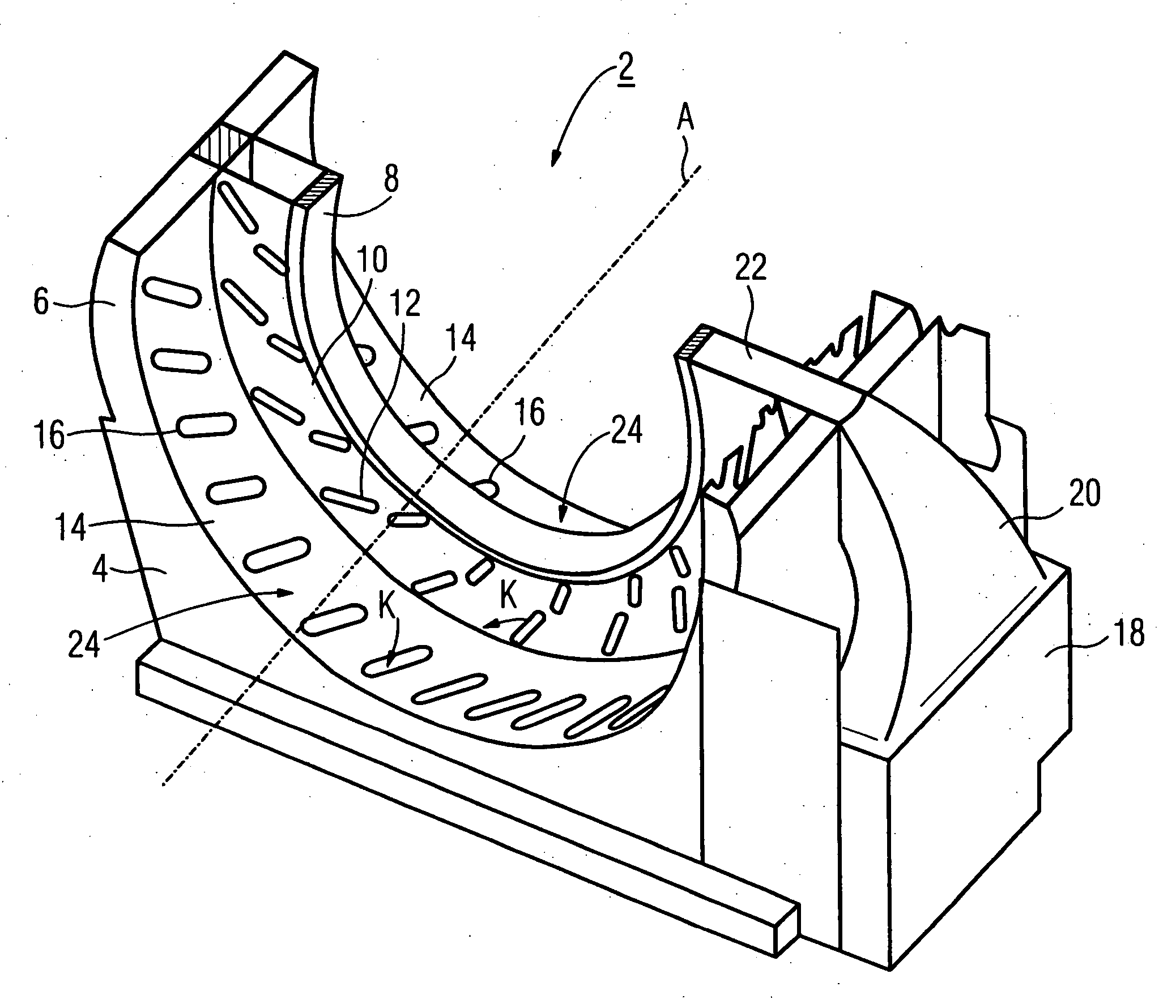
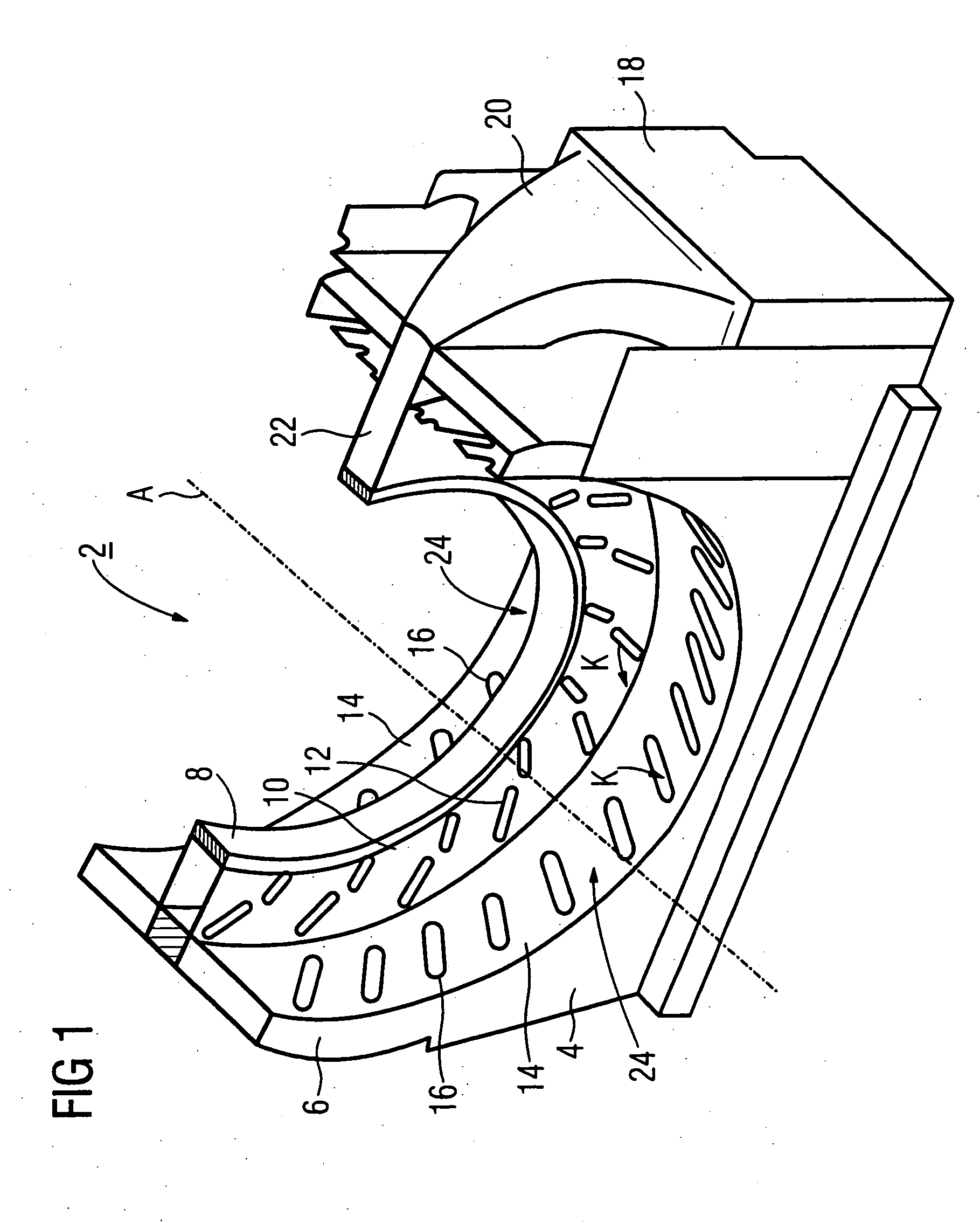
[0033]FIG. 1 shows a perspective view of a part of a gantry 2. The gantry 2 has a supporting body 4 that has an opening and the lower half of a support ring 6. The supporting body 4 and the support ring 6 are fashioned as one piece and are integrated with one another. The support ring 6 is arranged rotationally symmetrically with respect to an axis A that indicates its axial direction. The support ring 6 has a cooling ring 8 on its radially-inward circumferential side. Both flanks 10 of the cooling ring 8 are provided with outlets 12 that form two rows in the circumferential direction, and the outlets 12 of each row are approximately separated equally from one another. The cooling ring 8 exhibits a smaller axial extent than the support ring 8 and is centrally positioned on the support ring 6 such that two approximately equally large circumferential surfaces 14 are formed on both sides of the cooling ring. Each of the circumferential surfaces 14 exhibits a series of equidistant outle...
PUM
 Abstract
Description
Claims
Application Information