Wireless communication device and method

a communication device and wireless technology, applied in the direction of wireless communication, transmission monitoring, polarisation/directional diversity, etc., can solve the problems of speech quality deterioration, interference noise to other mobile stations, and deviation of the direction obtained, so as to improve the communication quality

Inactive Publication Date: 2007-03-08
FUJITSU LTD
View PDF15 Cites 14 Cited by
  • Summary
  • Abstract
  • Description
  • Claims
  • Application Information

AI Technical Summary

Benefits of technology

[0031] According to the present invention, it is possible to actualize the wireless communication...

Problems solved by technology

Thus, if the arrival angle spread is large, the conventional system has a problem that the beam direction obtained deviates, and a speech quality for a target mobile station deteriorates.
Further, in the W-CDMA (Wideband Code Division Multiple Access) system,...

Method used


Image

  • Wireless communication device and method
  • Wireless communication device and method
  • Wireless communication device and method

Examples


first embodiment

[0067] To start with, the wireless communication system in a first embodiment of the present invention will hereinafter be explained.

[0068] [System Architecture]

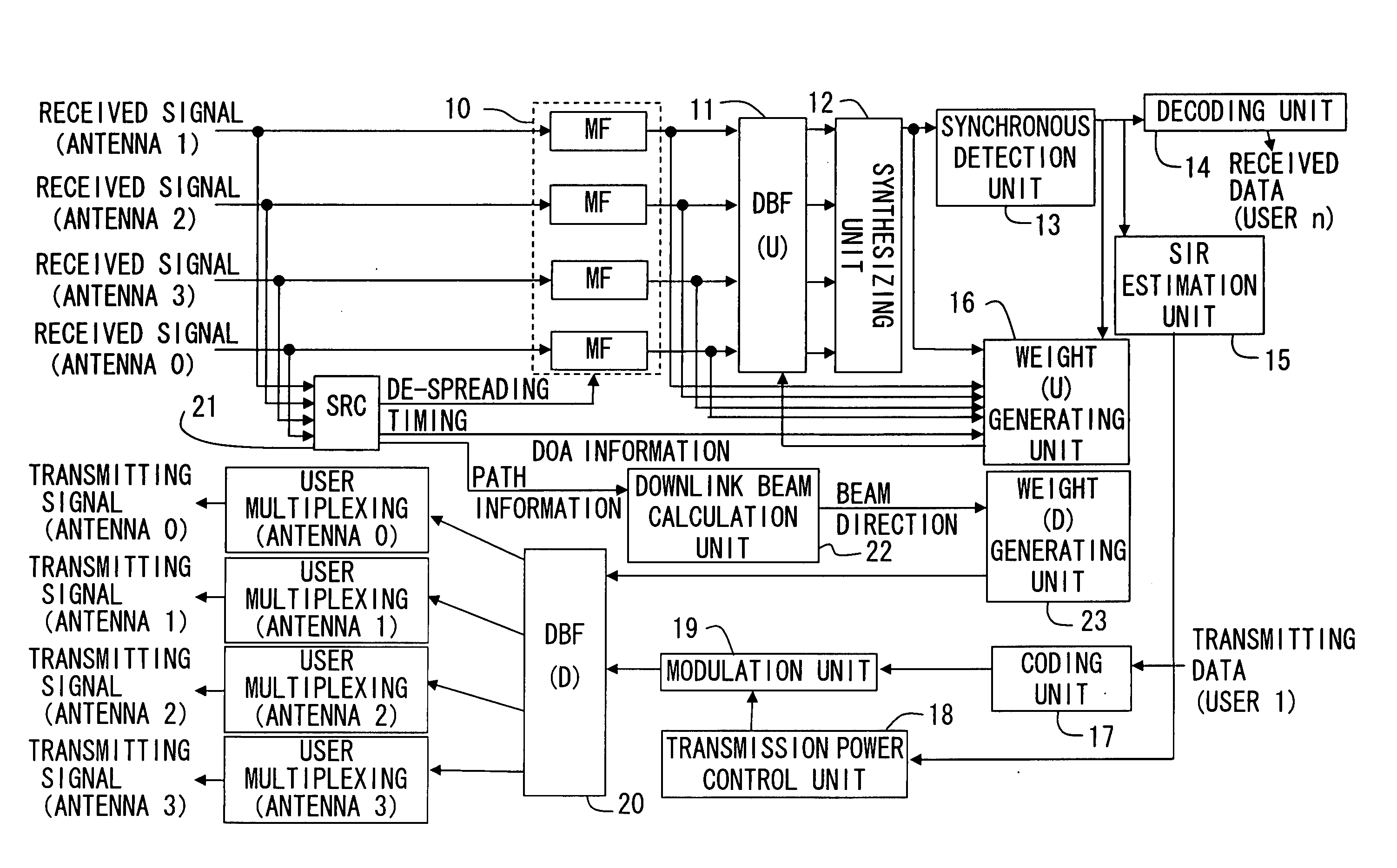
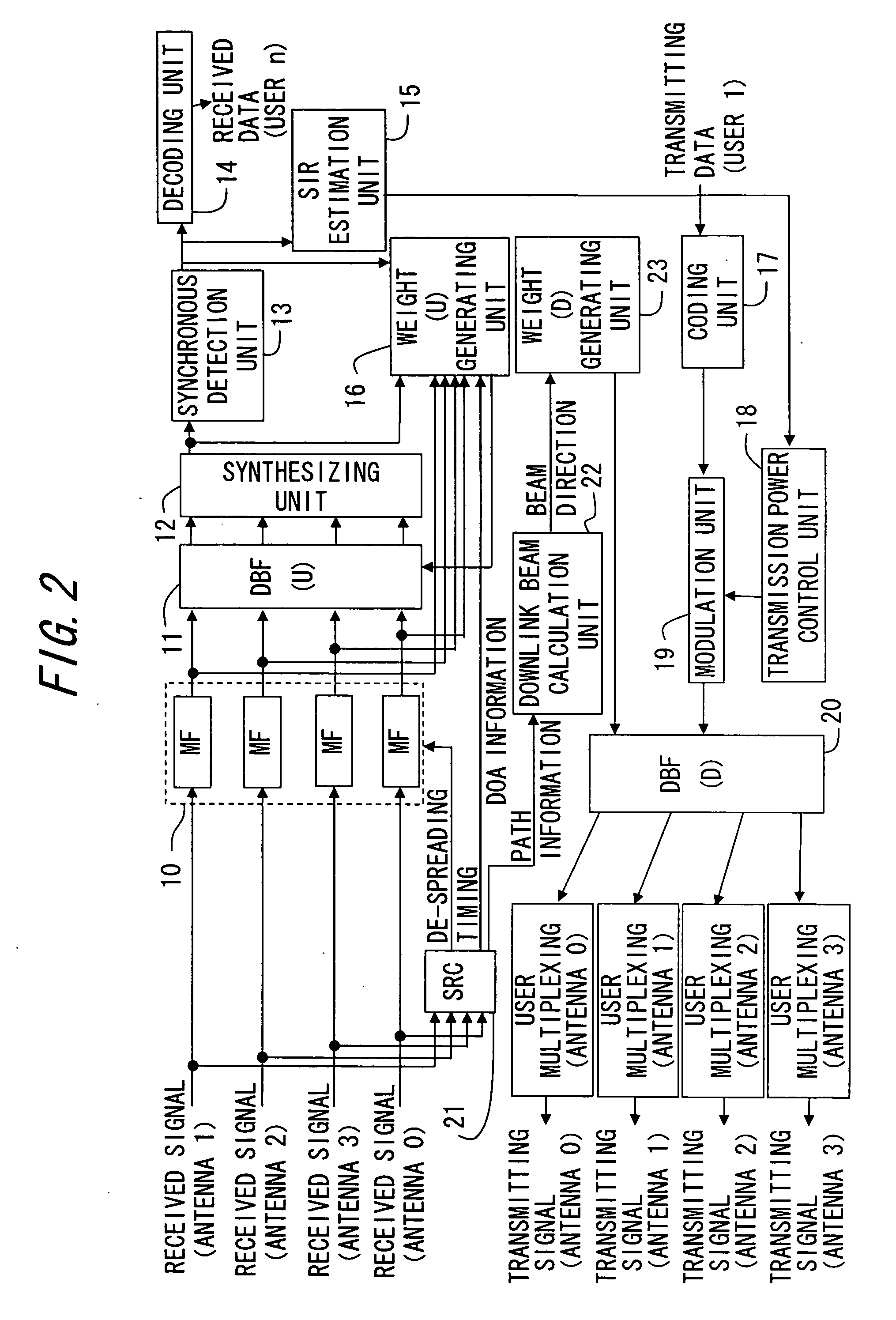
[0069] A system architecture of the wireless communication system (which will hereafter be simply referred to as this system) in the first embodiment, will be described with reference to FIGS. 2, 3 and 4. FIG. 2 is a block diagram showing the system architecture of the wireless communication system in the first embodiment. FIG. 3 is a block diagram showing a functional configuration of a downlink beam calculation unit in the first embodiment. FIG. 4 is a diagram showing a delay profile in the first embodiment.

[0070] This system includes a CPU (Central Processing Unit), a memory, an input / output interface, etc., and this CPU executes a control program etc. stored on the memory, thereby controlling respective function units given below. Further, the individual function units shown below may be set to operate by hardware logi...

second embodiment

[0109] The wireless communication system in a second embodiment of the present invention will hereinafter be described. The wireless communication system in the first embodiment explained earlier is that the beam coefficient k(i) is calculated by use of the delay information from the fast path, and the downlink beam direction is calculated by employing the beam coefficient k(i), the received signal power information P(i) and the arrival angle information θ(i) of each path. The wireless communication system in the second embodiment is that the beam coefficient k(i) is calculated by use of the delay information from the path having the maximum received signal power level (which will hereinafter be termed the maximum path) among the plurality of paths.

[0110] [System Architecture]

[0111] The wireless communication system in the second embodiment is configured by the same function units as those in the first embodiment (see FIG. 2). The downlink beam calculation unit 22, however, operate...

third embodiment

[0129] The following is a description of the wireless communication system in a third embodiment of the present invention. In the wireless communication system in the first embodiment discussed earlier, the downlink beam direction is calculated by use of the delay information from the fast path. The wireless communication system in the third embodiment is that the beam coefficient k(i) is calculated by using the delay information from a start timing for a path search in each path.

[0130] [System Architecture]

[0131] The wireless communication system in the third embodiment is configured by the same function units as those in the first embodiment (see FIG. 2). The downlink beam calculation unit 22, however, operates differently from in the first embodiment and is therefore explained as below. The explanations of the same other function units as those in the first embodiment are omitted. FIG. 7 is a block diagram showing a functional configuration of the downlink beam calculation unit ...


PUM


Abstract

The present invention provides a wireless communication device improving a communication quality by properly determining a beam transmitting direction. The wireless communication device has antennas receiving signals transmitted from a terminal respectively through a plurality of paths, a detection unit detecting each of a received timing, arrival angle information and received signal power information of each of the received signals, a delay information calculation unit obtaining delay information from the fastest received timing among the detected received timings or a start timing for a path search with respect to each of the received signals, a weighted coefficient calculation unit calculating a weighted coefficient with respect to each of the received signals based on the obtained delay information, and a determining unit determining a direction of the signal transmitted toward the terminal by using arrival angle information and the weighted coefficient.

Description

BACKGROUND OF THE INVENTION [0001] 1. Field of the Invention [0002] The present invention relates to a wireless communication device performing communications in a way that forms beams. [0003] 2. Description of the Related Art [0004] At the present, in a digital wireless communication field, there are developed a variety of technologies enabling high-speed communications in a wide band by improving a communication quality. [0005] One of these technologies is an adaptive array antenna technology. The adaptive array antenna technology is that an array antenna constructed of a plurality of antenna elements is used, and a signal transmitted and received by each antenna element is multiplied by a weighted coefficient corresponding to a propagation environment, thereby controlling directivity of the signal. With this contrivance, the adaptive array antenna technology enables interference waves to be suppressed and, more essentially, the communication quality to be improved. [0006] In a co...

Claims


Application Information

Patent Timeline
IPC IPC(8): H04B1/00H04B17/00H04M1/00H04B1/707H04B1/7113H04B7/08H04B7/10H04W16/28
CPCH04B7/086H04B7/0617
Inventor SATO, TOMONORI
Owner FUJITSU LTD
Why Eureka
Try Eureka