Optical disc device

Inactive Publication Date: 2007-03-15
HITACHI CONSUMER ELECTRONICS CORP
View PDF9 Cites 0 Cited by
  • Summary
  • Abstract
  • Description
  • Claims
  • Application Information

AI Technical Summary

Benefits of technology

[0012] The present invention is aimed at preventing a collision between the lens and the disc when the optical disc device is applied an impact acceleration even in a state with limited functions in use.
[0013] This objective is acc

Problems solved by technology

In the above conventional method that avoids collision between a lens and an optical disc by using an impact sensor and applying a force to the lens upon detecting an impact, since the servo control system is

Method used


Image

  • Optical disc device
  • Optical disc device
  • Optical disc device

Examples


embodiment 1

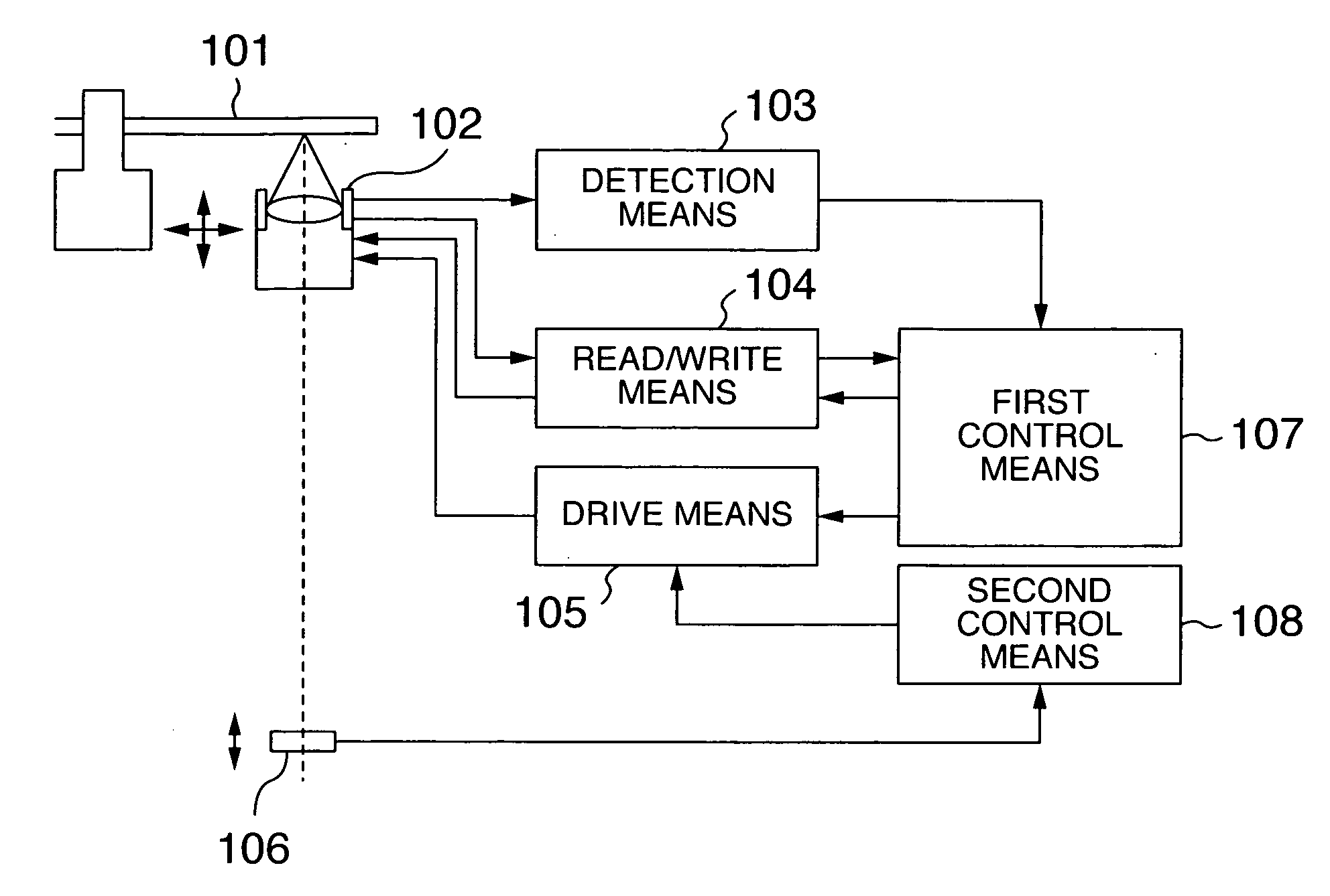
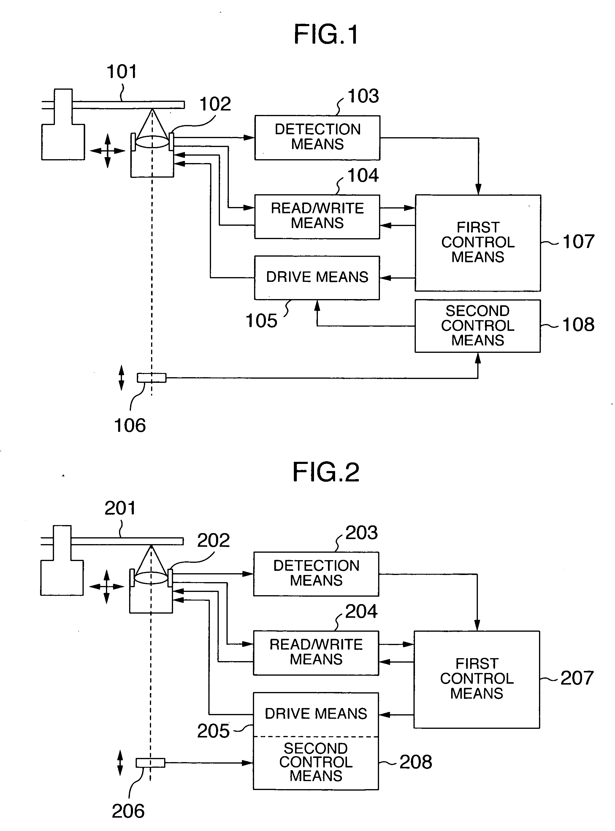
[0024]FIG. 1 is a block diagram showing a configuration of the optical disc device as one embodiment of this invention.

[0025] In FIG. 1, denoted 101 is an optical disc; 102 an optical head of a construction capable of driving the lens in a focus direction and in a tracking direction; 103 a detection means to detect a focus shift and a track shift of a beam spot on the optical disc 101 from a reflected beam that the optical head 102 has received from the optical disc 101; 104 a read / write means to read and write information from and to the optical disc 101; 105 a drive means to drive the lens installed in the optical head 102; 106 an acceleration detection means to measure an impact acceleration applied to the device; 107 a first control means to control the detection means, the read / write means and the drive means; and 108 a second control means capable of being operated independently of the first control means 107.

[0026] For accurate positioning of the beam spot on the disc, the ...

embodiment 2

[0039]FIG. 5 shows in a block diagram a configuration of an optical disc device as a second embodiment of this invention.

[0040] In FIG. 5, denoted 501 is an optical disc;. 502 an optical head having a construction capable of driving the lens in the focus direction and tracking direction; 503 a detection means to detect a focus shift and a track shift of a beam spot on the optical disc 501 from a reflected beam that the optical head 502 has received from the optical disc 501; 504 a read / write means to read and write information from and to the optical disc 501; 505 a drive means to drive the lens installed in the optical head 502; 506 an acceleration detection means to measure an impact acceleration applied to the device; 507 a first control means to control the detection means, the read / write means and the drive means; and 508 a second control means capable of being operated independently of the first control means 507.

[0041] In the example of FIG. 5 also, for accurate positioning...

embodiment 3

[0048]FIG. 6 in a block diagram a configuration of an optical disc device as a third embodiment of this invention.

[0049] In FIG. 6, denoted 601 is an optical disc; 602 an optical head having a construction capable of driving the lens in the focus direction and tracking direction; 603 a detection means to detect a focus shift and a track shift of a beam spot on the optical disc 601 from a reflected beam that the optical head 602 has received from the optical disc 601; 604 a read / write means to read and write information from and to the optical disc 601; 605 a drive means to drive the lens installed in the optical head 602; 606 an acceleration detection means to measure an impact acceleration applied to the device; 607 a first control means to control the detection means, the read / write means and the drive means; 608 a second control means capable of being operated independently of the first control means 607; and 609 a memory means to temporarily store data to be written into the op...


PUM


Abstract

In a conventional method for preventing a collision between a lens and an optical disc which uses a control system similar to the servo control of the optical disc, it is feared that, when there is no need to apply the servo, the collision prevention method may not perform its function satisfactorily. In an optical disc device that operates with a part of its functions suspended for reduced power consumption, the conventional method is not enough to avoid the collision between the lens and the optical disc. By arranging the lens/disc collision prevention mechanism independently operable, it is possible to prevent the collision between the lens and the disc even during the operation with limited functions.

Description

INCORPORATION BY REFERENCE [0001] The present application claims priority from Japanese application JP2005-267859 filed on Sep. 15, 2005, the content of which is hereby incorporated by reference into this application. BACKGROUND OF THE INVENTION [0002] 1. Field of the Invention [0003] The present invention relates to a construction of an optical disc and a lens in an optical disc device. [0004] 2. Description of the Related Art [0005] Optical disc devices converge a laser beam on an optical disc by a lens to read and write information. These devices employ a servo control for focusing which involves reading a focus deviation from a reflected beam and feeding it back to drive an actuator for the lens so that a spot of the converged laser beam is focused on a recording surface of the optical disc. [0006] As the recording density of optical discs has increased in recent years, a reduction in a diameter of laser spot has been under study. The study includes using a lens of high numerica...

Claims


Application Information

Patent Timeline
IPC IPC(8): G11B27/36
CPCG11B7/0956G11B21/12G11B7/1201G11B7/121
Inventor MATSUDA, TAKAHIROFUJITA, KOUJI
Owner HITACHI CONSUMER ELECTRONICS CORP
Why Eureka
Try Eureka