Slip-controlled, wound-rotor induction machine for wind turbine and other applications

a wound-rotor induction machine, slip-controlled technology, applied in the control of dynamo-electric converters, control systems, electric generators, etc., can solve the problems of machine b>10/b> operation, relatively high cost of full-power-rated power converters, and the lik

Inactive Publication Date: 2007-03-22
PERFECT GALAXY INT
View PDF13 Cites 45 Cited by
  • Summary
  • Abstract
  • Description
  • Claims
  • Application Information

AI Technical Summary

Problems solved by technology

Variable rotational speeds can be problematic, however, because, when delivering electrical power to a load, especially when delivering power to an alternating current (“AC”) utility grid, current at a constant-frequency, such as 50 or 60 Hertz (Hz), is desired.
Disadvantageously, some prior art systems restrict machine 10 operation either to a super-synchronous mode of operation or to a sub-synchronous mode of operation.
However, a major disadvantage of full-power, double-conversion schemes and field-oriented control is the relatively high cost of full-power-rated power converters.

Method used


Image

  • Slip-controlled, wound-rotor induction machine for wind turbine and other applications
  • Slip-controlled, wound-rotor induction machine for wind turbine and other applications
  • Slip-controlled, wound-rotor induction machine for wind turbine and other applications

Examples


Embodiment Construction

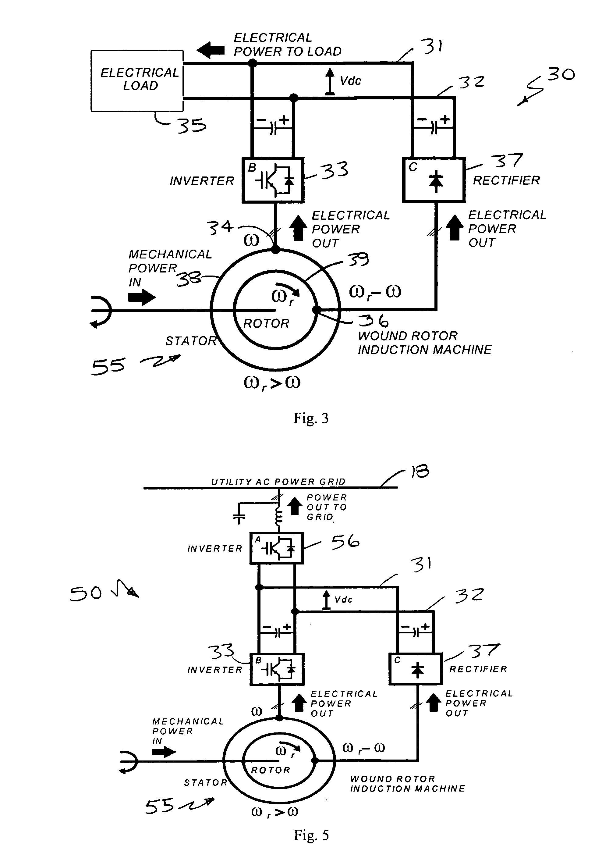
[0036] A system and method for converting mechanical power from a variable-speed, mechanical-energy source into direct current (“DC”) electrical power (current) delivered to a DC load bus with a regulated DC voltage is disclosed. More specifically, a slip-controlled, wound rotor induction machine generator 30 (“WRIMG”) is disclosed.

[0037] Referring to FIG. 3, the disclosed WRIMG 30 operates as a generator converting mechanical input power into electrical output power. More particularly, the WRIMG 30 delivers DC, i.e., zero frequency, power (current) to a pair of DC load bus lines 31 and 32 having a regulated, constant or substantially constant DC voltage (VDC). The DC load bus lines 31 and 32 are coupled to an electrical load 35 that is capable of absorbing power from a constant voltage DC source. The electrical load 35 can use the DC power directly, e.g., for heating, or can further convert it for various purposes, e.g., for transferring power to an AC electrical power grid.

[0038...


PUM


Abstract

A system and method for providing constant-frequency electrical power from variable-speed mechanical power are disclosed. The system includes a wound-rotor induction machine generator (WRIMG), a first power converter, e.g., an inverter or a bridge rectifier, that provides power from the stator assembly of the WRIMG to the load, and a second power converter, e.g., an inverter or a bridge rectifier, that provides power from the rotor assembly of the WRIMG to the load. A controller controls the output stator-current based on comparisons between measured DC load bus data and a reference DC load bus voltage value, measured machine shaft angular position and reference rotor frequency data, and measured stator-current data that is fed-back to the stator-current controller by the power converter device(s).

Description

CROSS REFERENCE TO RELATED APPLICATIONS [0001] This application claims the benefit of U.S. provisional patent application No. 60 / 718,088 filed on Sep. 16, 2005, which is incorporated herein in its entirety by reference.STATEMENT REGARDING FEDERALLY SPONSORED RESEARCH OR DEVELOPMENT [0002] N / A BACKGROUND OF THE INVENTION [0003] The present invention relates, in general, to a system and method for inductively converting variable-speed mechanical power into constant-frequency electrical power and, more specifically, to a system and method for controlling the load bus voltage of a variable-speed, wound-rotor induction machine to provide electrical power at a constant-frequency. [0004] There has been an increasing interest in non-fossil fuel energy sources as a consequence of the escalating cost and political ramifications associated with a reliance on foreign oil. Wind turbine generators (“WTGs”) are one of many current sources that provide an environmentally-friendly, non-polluting ene...

Claims


Application Information

Patent Timeline
Patent Type & Authority Applications(United States)
IPC IPC(8): H02P9/00H02H7/06H02P11/00
CPCH02P9/42H02P2101/15H02P23/08H02P9/46
Inventor SCHAUDER, COLIN DAVID
Owner PERFECT GALAXY INT
Why Eureka
Try Eureka