Zoom lens system

a zoom lens and zoom technology, applied in the field of zoom lens system, can solve the problems of high zoom ratio zoom lens system, insufficient optical performance, camera shake caused by a photographer, etc., and achieve the effect of superb optical performance and compactness

Active Publication Date: 2007-03-29
NIKON CORP
View PDF7 Cites 13 Cited by
  • Summary
  • Abstract
  • Description
  • Claims
  • Application Information

AI Technical Summary

Benefits of technology

[0015] The present invention is made in view of the aforementioned problems and has an object to provide a zoom lens system suitable for a video camera and an electronic still camera using a solid-state imaging device and the like, having a zoom ratio of about five or more with superb optical performance and compactness.
[0016] In view of vibration reduction, the present invention has an object to provide a zoom lens system suitable for a video camera and an electronic still camera using a solid-state imaging device and the like, having a zoom ratio of about five or more with compactness and superb optical performance even if a portion of the optical system is shifted substantially perpendicularly to the optical axis.

Problems solved by technology

On the other hand, a high zoom ratio zoom lens system has a problem that a camera shake caused by a photographer tends to occur on the telephoto side.
Although both of these requirements have to be satisfied simultaneously, in the zoom lens systems disclosed in Japanese Patent Application Laid-Open No. 2002-98893, optical performance is not sufficiently high over entire focal length range from the wide-angle end state to the telephoto end state and although a high zoom ratio is secured, compactness is not sufficient.
On the other hand, while the request for the function of canceling a camera shake recently becomes high, in the zoom lens systems disclosed in Japanese Patent Application Laid-Open No. 2003-207715, optical performance is not sufficiently high over entire focal length range from the wide-angle end state to the telephoto end state and optical performance upon shifting a portion of the optical system substantially perpendicularly to the optical axis is not sufficiently high.
In addition, the zoom ratio is not sufficient since it is less than five.
Although various zoom lens systems of this kind have been proposed in Japanese Patent Application Laid-Open Nos. 2004-252196, 10-260356, 11-23969, 2000-298235, and 2003-177318, any one of them has satisfied not all requirements such as a sufficient zoom ratio, an enough angle of view in the wide-angle end state, compactness, and good optical performance.

Method used


Image

  • Zoom lens system
  • Zoom lens system
  • Zoom lens system

Examples


first embodiment

[0180] A zoom lens system according to a first embodiment of the present invention is composed of, in order from an object along an optical axis, a first lens group having positive refractive power, a second lens group having negative refractive power, a third lens group having positive refractive power, a fourth lens group having positive refractive power, and a fifth lens group having positive refractive power.

[0181] In a video camera and an electronic still camera using a solid-state imaging device and the like, a zoom lens system is required to have an exit pupil locating far away from an image plane because of the characteristics of the imaging device, so that it is preferable that the lens group locating near to the image plane has positive refractive power as a whole.

[0182] Accordingly, in the zoom lens system according to the first embodiment of the present invention, the above-mentioned requirement is satisfied by constructing, in order from an object along the optical ax...

example 1

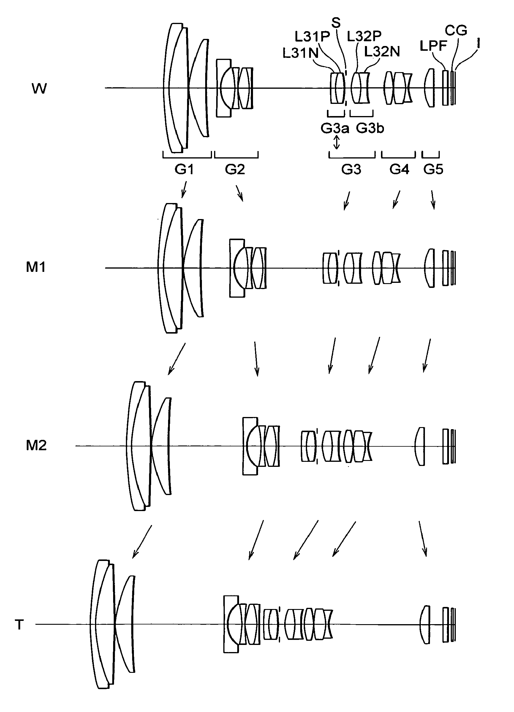
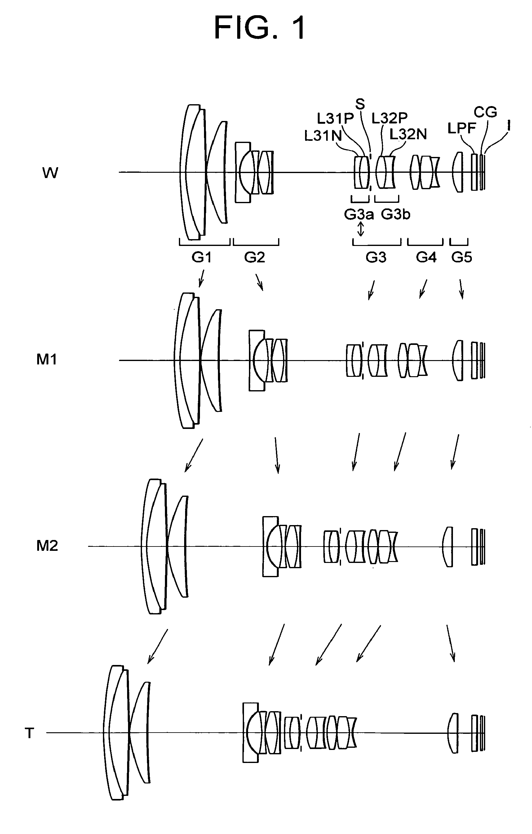
[0259]FIG. 1 shows cross-sectional views of a zoom lens system according to Example 1 of the first embodiment of the present invention upon focusing on infinity in which, in order from top to bottom, a wide-angle end state (W), a wide-angle side intermediate focal length state (M1), a telephoto side intermediate focal length state (M2), and a telephoto end state (T) are shown, respectively.

[0260] The zoom lens system according to Example 1 is composed of, in order from an object along an optical axis, a first lens group G1 having positive refractive power, a second lens group G2 having negative refractive power, a third lens group G3 having positive refractive power, a fourth lens group G4 having positive refractive power, and a fifth lens group G5 having positive refractive power.

[0261] In the zoom lens system according to Example 1, when the state of lens group positions varies from the wide-angle end state to the telephoto end state upon focusing on infinity, the first lens gro...

example 2

[0283]FIG. 6 shows cross-sectional views of a zoom lens system according to Example 2 of the first embodiment of the present invention upon focusing on infinity in which, in order from top to bottom, a wide-angle end state (W), a wide-angle side intermediate focal length state (M1), a telephoto side intermediate focal length state (M2), and a telephoto end state (T) are shown, respectively.

[0284] The zoom lens system according to Example 2 is composed of, in order from an object along an optical axis, a first lens group G1 having positive refractive power, a second lens group G2 having negative refractive power, a third lens group G3 having positive refractive power, a fourth lens group G4 having positive refractive power, and a fifth lens group G5 having positive refractive power.

[0285] In the zoom lens system according to Example 2, when the state of lens group positions varies from the wide-angle end state to the telephoto end state upon focusing on infinity, the first lens gro...


PUM


Abstract

A zoom lens system includes, in order from an object, a first lens group having positive power, a second lens group having negative power, a third lens group having positive power, a fourth lens group having positive power, and a fifth lens group having positive power. Upon zooming from a wide-angle end state to a telephoto end state, the first and fifth lens groups moves with respect to the image plane, the second lens group moves at first to the image and then to the object, and the third and fourth lens groups move to the object such that a distance between the first and second lens groups increases, a distance between the second and third lens group decreases, a distance between the third and fourth lens groups decreases, and a distance between the fourth and fifth lens groups increases. Given conditional expressions are satisfied.

Description

[0001] The disclosure of the following priority applications are herein incorporated by reference: [0002] Japanese Patent Application No. 2004-268961 filed on Sep. 15, 2004, [0003] Japanese Patent Application No. 2005-098725 filed on Mar. 30, 2005, [0004] Japanese Patent Application No. 2005-098737 filed on Mar. 30, 2005, [0005] Japanese Patent Application No. 2005-196621 filed on Jul. 5, 2005, and [0006] Japanese Patent Application No. 2005-196624 filed on Jul. 5, 2005. BACKGROUND OF THE INVENTION [0007] 1. Field of the Invention [0008] The present invention relates to a zoom lens system suitable for a video camera and an electronic still camera using a solid-state imaging device and the like. [0009] 2. Related Background Art [0010] A lot of zoom lens systems suitable for a video camera and an electronic still camera using a solid-state imaging device and the like as an imaging medium have been proposed. Among them, it has been known that those having a high zoom ratio of five or m...

Claims


Application Information

Patent Timeline
Patent Type & Authority Applications(United States)
IPC IPC(8): G02B15/14
CPCG02B27/646G02B15/173G02B15/145129
Inventor OBAMA, AKIHIKOTAKE, TOSHINORI
Owner NIKON CORP
Why Eureka
Try Eureka