Zoom lens system

Active Publication Date: 2005-03-31
NIKON CORP
View PDF1 Cites 19 Cited by
  • Summary
  • Abstract
  • Description
  • Claims
  • Application Information

AI Technical Summary

Benefits of technology

The present invention is made in view of the aforementioned problems and has an object to provide a zoom lens system having superb optical performance and compactness by using a diffractive optical element.

Problems solved by technology

However, it has been very difficult to satisfy both high optical performance (in particular, color drift) and compactness with a simple mechanism in accordance with recent progress in imaging technology such as miniaturizing the pixel pitch of an imaging device.

Method used


Image

  • Zoom lens system
  • Zoom lens system
  • Zoom lens system

Examples


example 1

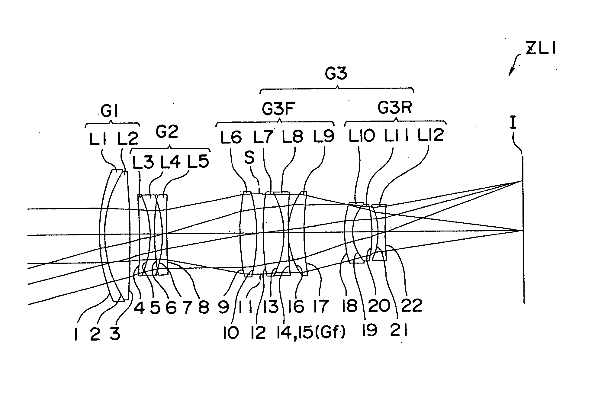
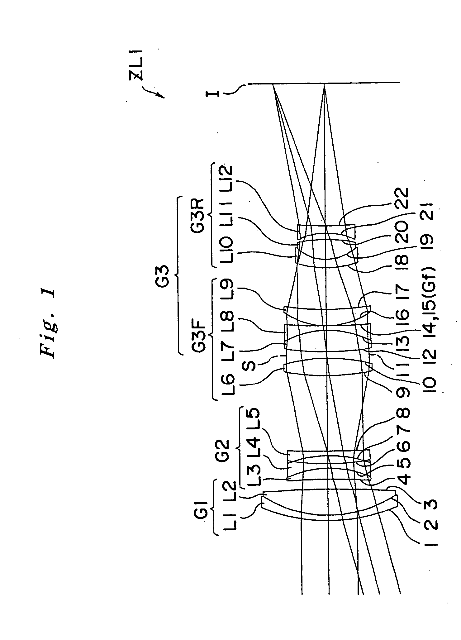
Example 1 of the present invention is explained below with reference to FIGS. 1 through 4. FIG. 1 is a diagram showing lens construction of a zoom lens system according to Example 1 of the present invention. In a zoom lens system ZL1 used in Example 1, as shown in FIG. 1, a first lens group G1 having positive refractive power is composed of, in order from an object, a cemented lens constructed by a negative meniscus lens L1 having a convex surface facing to the object cemented with a double convex lens L2. A second lens group G2 having negative refractive power is composed of, in order from the object, a cemented lens constructed by a positive meniscus lens L3 having a convex surface facing to an image cemented with a double concave lens L4 and a double concave lens L5. A third lens group G3 having positive refractive power is composed of, in order from the object, a double convex lens L6, an aperture stop S, a cemented lens constructed by a double convex lens L7 cemented with a do...

example 2

Example 2 of the present invention is explained below with reference to FIGS. 5 through 8. FIG. 5 is a diagram showing lens construction of a zoom lens system according to Example 2 of the present invention. In a zoom lens system ZL2 used in Example 2, as shown in FIG. 5, a first lens group G1 having positive refractive power is composed of, in order from an object, a cemented lens constructed by a negative meniscus lens L1 having a convex surface facing to the object cemented with a double convex lens L2 and a negative meniscus lens L3 having a convex surface facing to the object. A second lens group G2 having negative refractive power is composed of, in order from the object, a cemented lens constructed by a positive meniscus lens L4 having a convex surface facing to an image cemented with a double concave lens L5 and a double concave lens L6. A third lens group G3 having positive refractive power is composed of, in order from the object, a double convex lens L7, an aperture stop...

example 3

Example 3 of the present invention is explained below with reference to FIGS. 9 through 12. FIG. 9 is a diagram showing lens construction of a zoom lens system according to Example 3 of the present invention. In a zoom lens system ZL3 used in Example 3, as shown in FIG. 9, a first lens group G1 having positive refractive power is composed of, in order from an object, a cemented lens constructed by a negative meniscus lens L1 having a convex surface facing to the object cemented with a double convex lens L2. A second lens group G2 having negative refractive power is composed of, in order from the object, a cemented lens constructed by a positive meniscus lens L3 having a convex surface facing to an image cemented with a double concave lens L4 and a double concave lens L5. A third lens group G3 having positive refractive power is composed of, in order from the object, a double convex lens L6, an aperture stop S, a cemented lens constructed by a double convex lens L7 cemented with a d...


PUM


Abstract

To provide a zoom lens system having high optical performance by using a diffractive optical element, the system includes a first group having positive power, a second group having negative power, and a third group having positive power. When zooming from a wide-angle end state to a telephoto end state, a distance between the first group and the second group and a distance between the second group and the third group vary. The third group is composed of a front group having positive power locating to the object side of the largest space in the third group and a rear group having negative power locating to an image side of the space. The front group includes an aperture stop and a diffractive optical surface. An incident angle of a principal ray reaching the maximum image height to the diffractive optical surface is ten degrees or less. Given condition is satisfied.

Description

INCORPORATION BY REFERENCE The disclosures of the following priority application is herein incorporated by reference: Japanese Patent Application No. 2003-337261 filed on Sep. 29, 2003. BACKGROUND OF THE INVENTION 1. Field of the Invention The present invention relates to a zoom lens system having a diffractive optical element suitable for a film camera, a video camera, and a digital still camera. 2. Related Background Art With the advance of technology, various types of zoom lens system have been proposed. As an optical system for a film camera, a video camera, and a digital still camera in particular, a three-group type zoom lens system, which is called a telephoto type, having a construction of, in order from an object, a positive-negative-positive power arrangement with a short back focal length. For such example, there is Japanese Paten Application Laid-Open No. 11-305126. However, it has been very difficult to satisfy both high optical performance (in particular, color ...

Claims


Application Information

Patent Timeline
IPC IPC(8): G02B13/18G02B15/173G02B15/20
CPCG02B15/173G02B15/143105
Inventor SUZUKI, KENZABURO
Owner NIKON CORP
Why Eureka
Try Eureka