Insulating boot for electrosurgical forceps

a technology of electrosurgical forceps and boot, which is applied in the field of insulated electrosurgical forceps, can solve the problems of reducing the possibility of stray, reducing the effect of stray forceps, and reducing the potential of stray forceps

Active Publication Date: 2007-04-05
COVIDIEN AG
View PDF99 Cites 314 Cited by
  • Summary
  • Abstract
  • Description
  • Claims
  • Application Information

AI Technical Summary

Benefits of technology

[0018] It would be desirous to provide electrosurgical instruments with a flexible insulating boot that both permits pivoting and other associated movements of the jaw members and also reduces the potential for stray or miscellaneous currents affecting surrounding tissue.

Problems solved by technology

Smaller cannulas are usually preferred, which, as can be appreciated, ultimately presents a design challenge to instrument manufacturers who must find ways to make endoscopic instruments that fit through the smaller cannulas.
Due to the inherent spatial considerations of the surgical cavity, surgeons often have difficulty suturing vessels or performing other traditional methods of controlling bleeding, e.g., clamping and / or tying-off transected blood vessels.
However, if a larger vessel is ligated, it may be necessary for the surgeon to convert the endoscopic procedure into an open-surgical procedure and thereby abandon the benefits of endoscopic surgery.
Below this range, the seal may shred or tear and above this range the lumens may not be properly or effectively sealed.
Many known instruments include blade members or shearing members which simply cut tissue in a mechanical and / or electromechanical manner and are relatively ineffective for vessel sealing purposes.
Other instruments rely on clamping pressure alone to procure proper sealing thickness and are not designed to take into account gap tolerances and / or parallelism and flatness requirements which are parameters which, if properly controlled, can assure a consistent and effective tissue seal.
For example, it is known that it is difficult to adequately control thickness of the resulting sealed tissue by controlling clamping pressure alone for either of two reasons: 1) if too much force is applied, there is a possibility that the two poles will touch and energy will not be transferred through the tissue resulting in an ineffective seal; or 2) if too low a force is applied the tissue may pre-maturely move prior to activation and sealing and / or a thicker, less reliable seal may be created.
This presents a design challenge because the jaw members are typically affixed with pins which are positioned to have small moment arms with respect to the pivot of each jaw member.
A large force, coupled with a small moment arm, is undesirable because the large forces may shear the pins.
Increasing the closure forces between electrodes may have other undesirable effects, e.g., it may cause the opposing electrodes to come into close contact with one another which may result in a short circuit and a small closure force may cause pre-mature movement of the tissue during compression and prior to activation.
As can be appreciated, relying on a surgeon to manually provide the appropriate closure force within the appropriate range on a consistent basis would be difficult and the resultant effectiveness and quality of the seal may vary.
However, a general issue with existing electrosurgical forceps is that the jaw members rotate about a common pivot at the distal end of a metal or otherwise conductive shaft such that there is potential for both the jaws, a portion of the shaft, and the related mechanism components to conduct electrosurgical energy (either monopolar or as part of a bipolar path) to the patient tissue.

Method used


Image

  • Insulating boot for electrosurgical forceps
  • Insulating boot for electrosurgical forceps
  • Insulating boot for electrosurgical forceps

Examples


Embodiment Construction

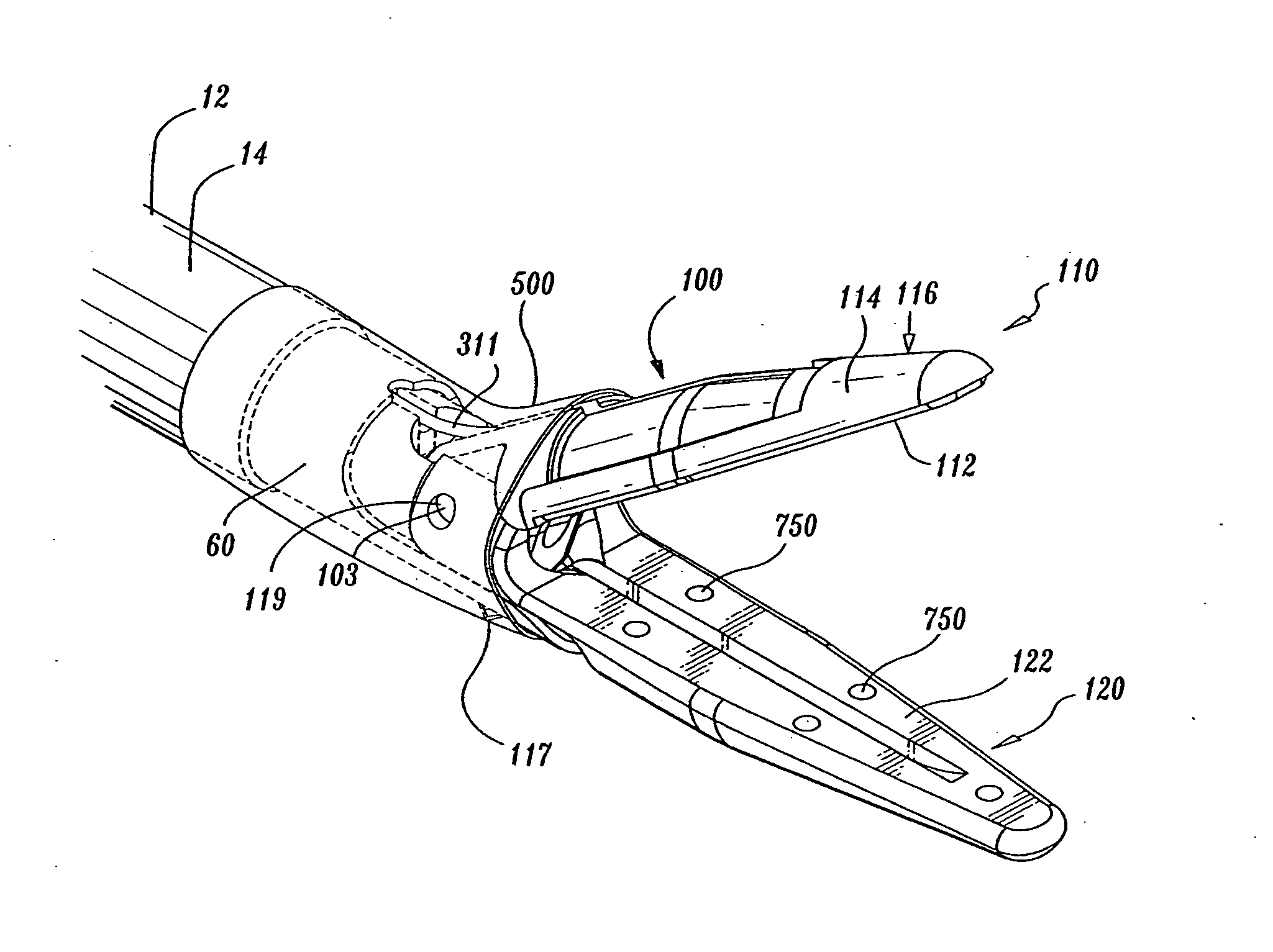
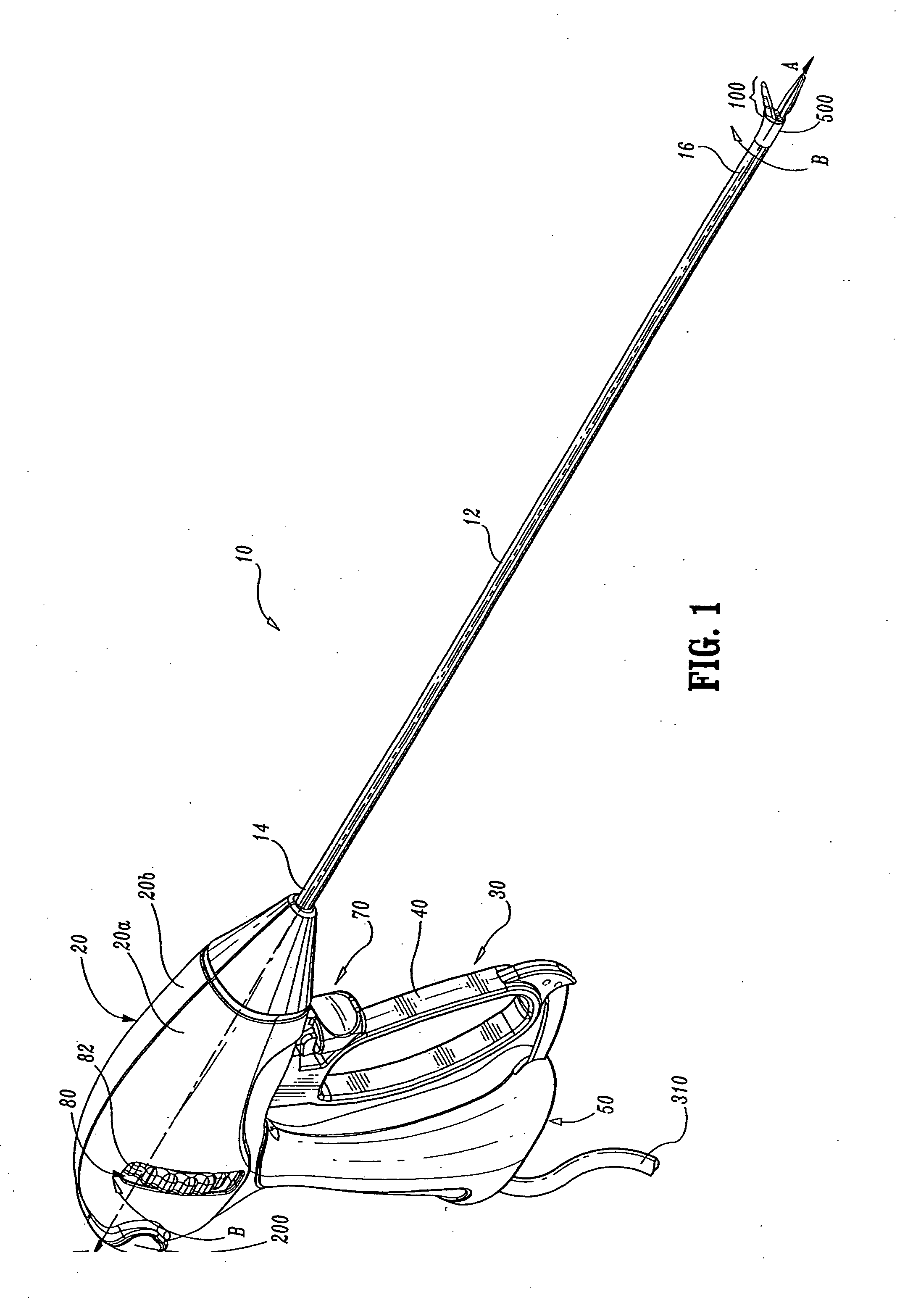
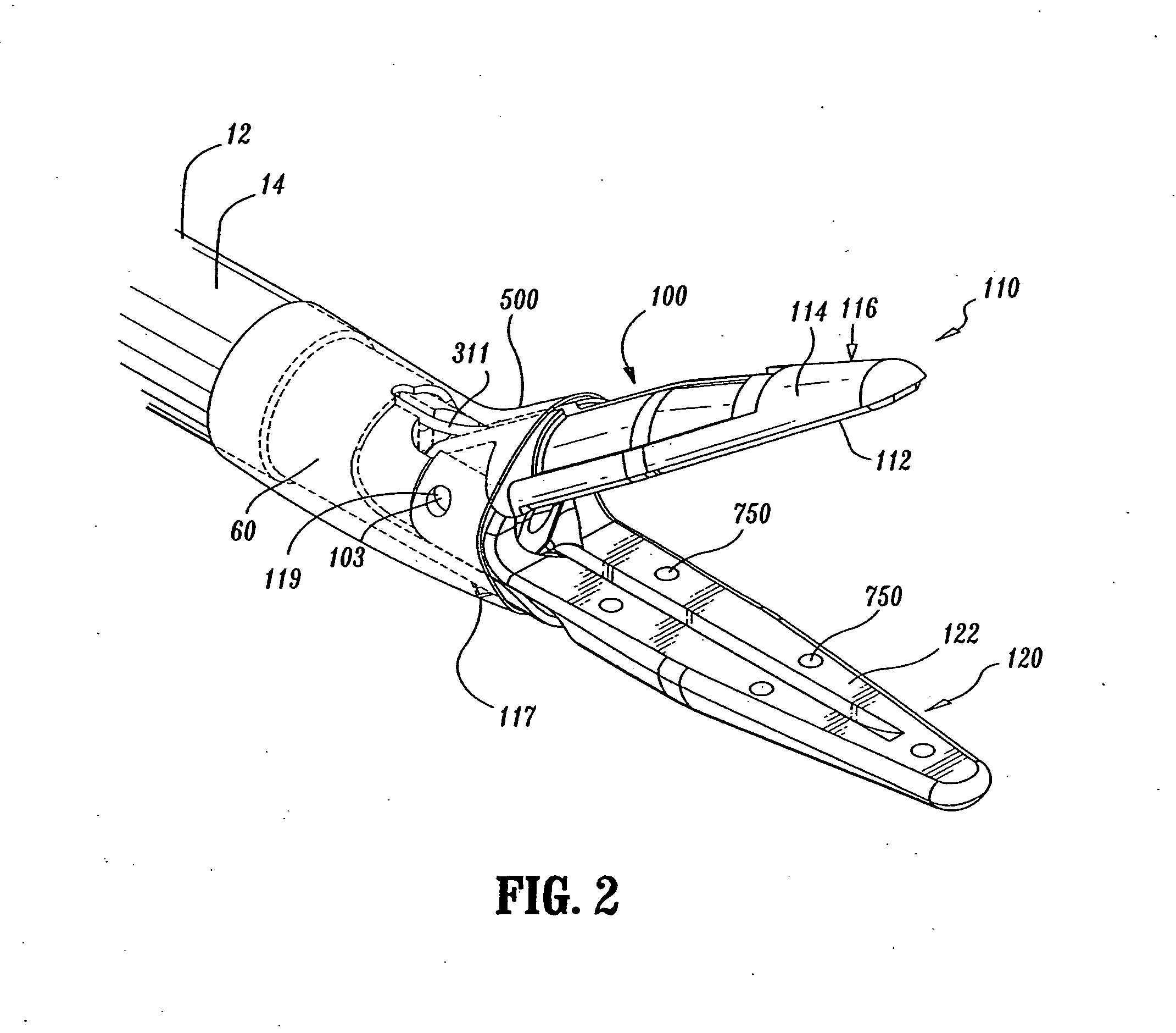
[0071] Referring initially to FIGS. 1-3, one particularly useful endoscopic forceps 10 is shown for use with various surgical procedures and generally includes a housing 20, a handle assembly 30, a rotating assembly 80, a trigger assembly 70, a knife assembly and an end effector assembly 100 that mutually cooperate to grasp, seal and divide tubular vessels and vascular tissue 420 (see FIGS. 18-19). For the purposes herein, forceps 10 will be described generally. However, the various particular aspects of this particular forceps are detailed in commonly owned U.S. patent applications Ser. No. 10 / 460,926, filed on Jun. 13, 2003, and entitled “VESSEL SEALER AND DIVIDER FOR USE WITH SMALL TROCARS AND CANNULAS,” and previously mentioned U.S. patent application Ser. No. 10 / 970,307, the entire contents of each of which are incorporated by reference herein. Forceps 10 includes a shaft 12 that has a distal end 16 dimensioned to mechanically engage the end effector assembly 100 and a proximal...


PUM


Abstract

Either an endoscopic or open bipolar forceps includes a flexible, generally tubular insulating boot for insulating patient tissue, while not impeding motion of the jaw members. The jaw members are movable from an open to a closed position and the jaw members are connected to a source of electrosurgical energy such that the jaw members are capable of conducting energy through tissue held therebetween to effect a tissue seal. A knife assembly may be included that allows a user to selectively divide tissue upon actuation thereof. The insulating boot may be made from a viscoelastic, elastomeric or flexible material suitable for use with a sterilization process including ethylene oxide.

Description

CROSS-REFERENCE TO RELATED APPLICATIONS [0001] This application claims the benefit of priority of U.S. Provisional Patent Application Ser. No. 60 / 722,213 by Scott DePierro et al., entitled “INSULATING BOOT FOR ELECTROSURGICAL FORCEPS” filed on Sep. 30, 2005, the entire contents of which is incorporated by reference herein. This application cross-references U.S. Provisional Patent Application Ser. No. 60 / 722,186 by Paul Guerra, entitled “METHOD FOR MANUFACTURING AN END EFFECTOR ASSEMBLY,” and U.S. Provisional Patent Application Ser. No. 60 / 722,359 by Kristin Johnson et al, entitled “FLEXIBLE ENDOSCOPIC CATHETER WITH LIGASURE,” both filed on Sep. 30, 2005, the entire contents of both applications being incorporated by reference herein.BACKGROUND [0002] 1. Technical Field [0003] The present disclosure relates to an insulated electrosurgical forceps and more particularly, the present disclosure relates to an insulating boot for use with either an endoscopic or open bipolar and / or monopo...

Claims


Application Information

Patent Timeline
Patent Type & Authority Applications(United States)
IPC IPC(8): A61B18/14
CPCA61B18/1442A61B18/1445A61B2017/2945A61B2018/00083A61B2018/0063A61B2018/1412A61B2018/1432A61B2018/1455A61B2018/1475A61B2019/304A61B2090/034
Inventor DUMBAULD, PATRICK L.GUERRA, PAULSMITH, ROGER F.DEPIERRO, SCOTT
Owner COVIDIEN AG
Why Eureka
Try Eureka