Eyeglasses with a heart rate monitor

a heart rate monitor and eyeglasses technology, applied in the field of eyeglasses with heart rate monitors, can solve the problems of unsatisfactory approach and inconvenient approach

Active Publication Date: 2007-05-17
INGENIOSPEC
View PDF99 Cites 131 Cited by
  • Summary
  • Abstract
  • Description
  • Claims
  • Application Information

AI Technical Summary

Benefits of technology

[0008] In one embodiment, the present invention provides a heart rate sensor attached to, integral with or tethered to a pair of glasses.

Problems solved by technology

This approach can be quite inconvenient because the person has to wear a band across his chest in order to get the necessary me

Method used


Image

  • Eyeglasses with a heart rate monitor
  • Eyeglasses with a heart rate monitor
  • Eyeglasses with a heart rate monitor

Examples


Embodiment Construction

[0029] In one embodiment, a pair of glasses for a user has a heart rate (heart beat) monitor. The heart rate monitor can be partially or fully embedded in the eyeglasses. For example, the heart rate monitor can be substantially embedded in a temple of the eyeglasses. In another embodiment, the heart rate monitor can be coupled (either permanently or temporarily) to the eyeglasses.

[0030] In one embodiment, the heart rate monitor can include an infrared sensor (or IR sensor) and processing circuitry. Using measurements from the infrared sensor, the processing circuitry can determine the user's heart rate. The eyeglasses can also include one or more output devices, such as a speaker or beeper, for audio output, and / or a display for visual output.

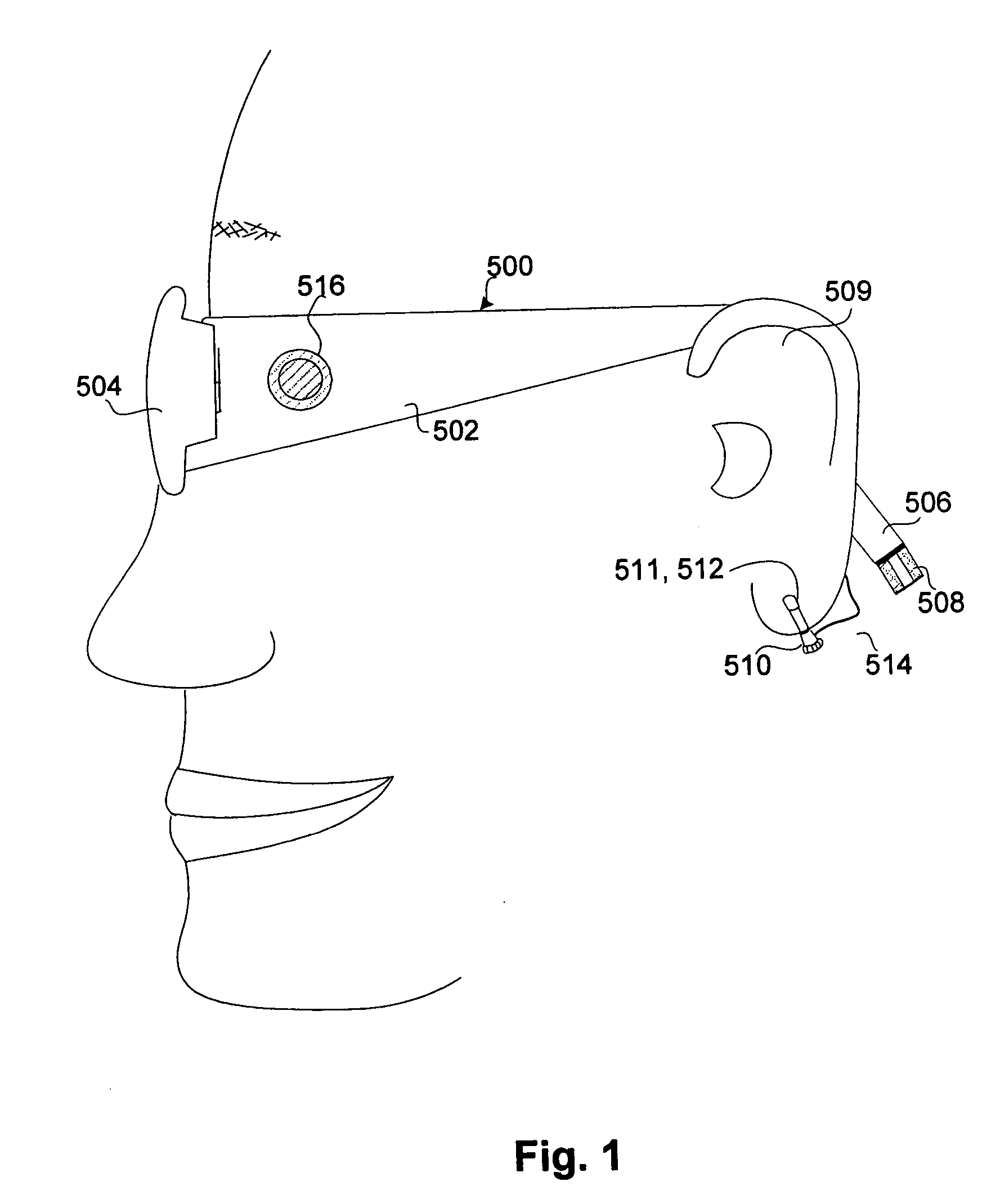
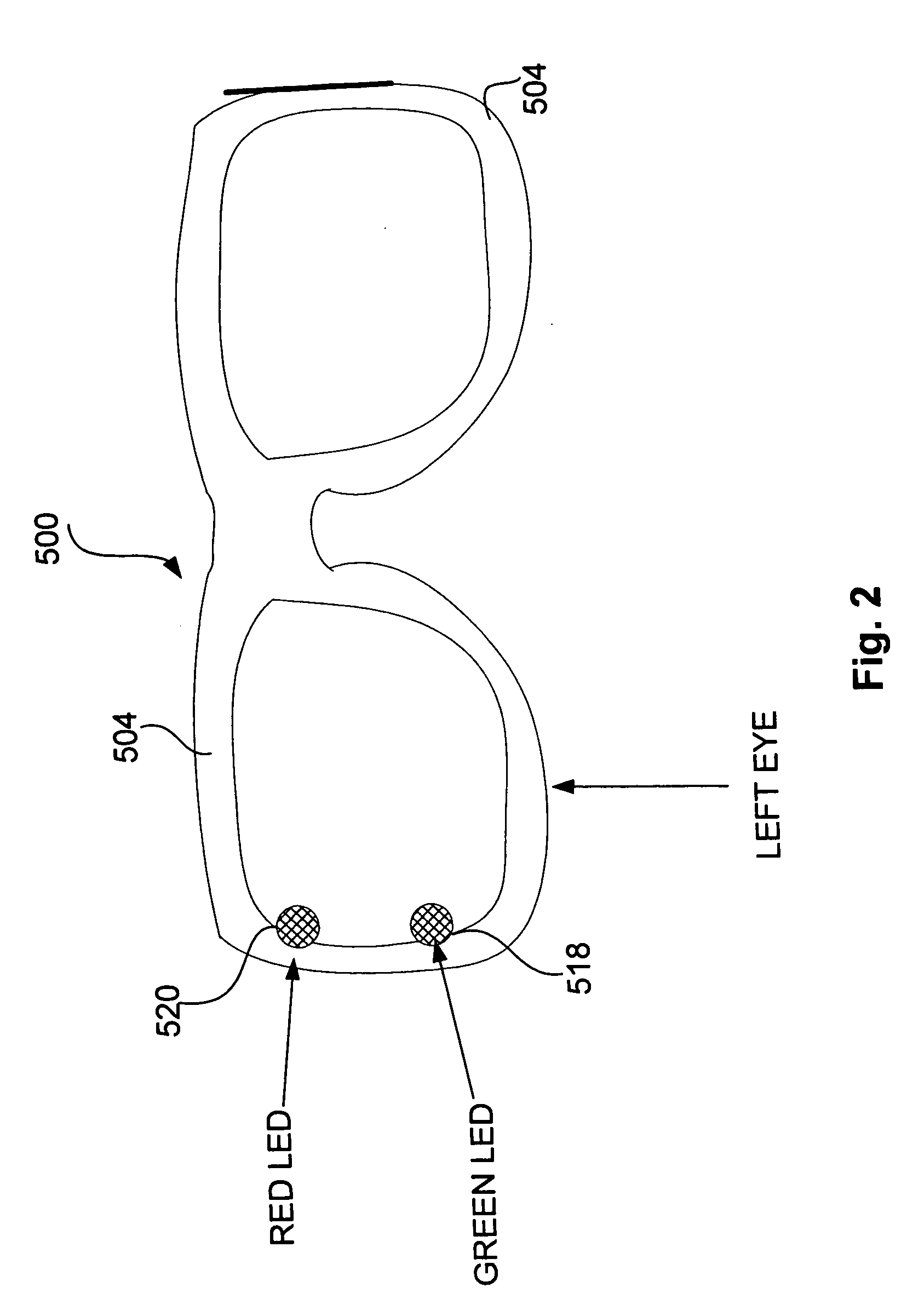
[0031]FIG. 1 illustrates a pair of eyeglasses 500 having heart rate monitoring capabilities according to one embodiment. The pair of eyeglasses 500 includes left and right temples 502 and left and right lens holders 504.

[0032] A rearward tem...


PUM


Abstract

A pair of glasses with a heart-rate monitor according to one embodiment. The heart-rate monitor is configured to measure the heart rate of the user of the glasses. The heart-rate monitor can include a sensor with a radiation transmitter and a radiation receiver. The radiation could be infrared radiation. In one approach, the receiver measures signals transmitted by the transmitter through a body part of the user to measure the user's heart rate. The sensor could be incorporated in a clip to clip onto the body part of the user, such as the ear lobe of the user. In another approach, the receiver measures signals transmitted by the transmitter and reflected by a body part of the user to measure the user's heart rate.

Description

CROSS-REFERENCE TO RELATED APPLICATIONS [0001] This application is a continuation-in-part of U.S. patent application Ser. No. 11 / 183,256, filed Jul. 15, 2005, and entitled “EYEGLASSES WITH ELECTRICAL COMPONENTS,” which is hereby incorporated herein by reference, which in turn is a continuation-in-part of U.S. patent application Ser. No. 10 / 964,011, filed Oct. 12, 2004, and entitled “TETHERED ELECTRICAL COMPONENTS FOR EYEGLASSES,” which is hereby incorporated herein by reference, which in turn claims priority to each of: (i) U.S. Provisional Patent Application No. 60 / 509,631, filed Oct. 9, 2003, and entitled “TETHERED ELECTRICAL COMPONENTS FOR EYEGLASSES,” which is hereby incorporated herein by reference; (ii) U.S. Provisional Patent Application No. 60 / 527,565, filed Dec. 8, 2003, and entitled “ADAPTABLE COMMUNICATION TECHNIQUES FOR ELECTRONIC DEVICES,” which is hereby incorporated herein by reference; (iii) U.S. Provisional Patent Application No. 60 / 562,798, filed Apr. 15, 2004, ent...

Claims


Application Information

Patent Timeline
IPC IPC(8): G02C5/00
CPCG02C5/001G02C11/10A61B5/02433A61B5/6803A61B5/6816A61B5/742
Inventor HOWELL, THOMAS A.CHAO, DAVIDTHOMAS, C. DOUGLASSDAY, ROBERT GRANTTONG, PETER P.
Owner INGENIOSPEC
Why Eureka
Try Eureka