Image coding device, method and computer program

a coding device and image technology, applied in the field of image coding devices, can solve the problems of large amount of data, and significant increase in the compression rate of image data, and achieve the effect of improving speed

Active Publication Date: 2007-06-14
PANASONIC CORP
View PDF6 Cites 37 Cited by
  • Summary
  • Abstract
  • Description
  • Claims
  • Application Information

AI Technical Summary

Benefits of technology

[0020] In order to solve the above problems, an object of the present invention is to provide an image co

Problems solved by technology

However, image data (especially moving picture data) has a large amount of data.
Therefore, when digital image data is coded and then broadcasted or transferred via a medium such as a DVD, the amount of the data becomes quite large.
Moreover, because of recent improvements in data processing ability of computers and other apparatuses, complicated arithmetic operations in the compression technologies have been realized, so th

Method used


Image

  • Image coding device, method and computer program
  • Image coding device, method and computer program
  • Image coding device, method and computer program

Examples


first example

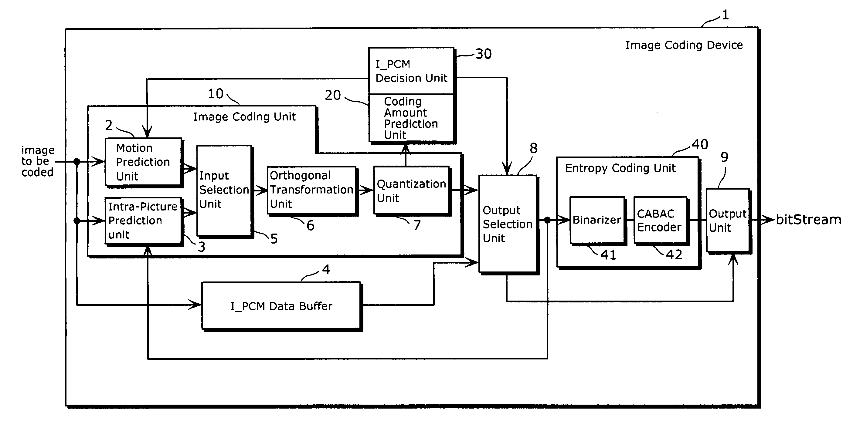
[0066]FIG. 4 is a block diagram showing the first example of the functional structure of the image coding device 1.

[0067] As shown in FIG. 4, the I_PCM decision unit 30 has a coding amount comparing unit 31 and a threshold value storage unit 32. Other units shown in FIG. 4 are identical to the units in FIG. 2.

[0068] The threshold value storage unit 32 is a storage unit, in which the threshold value regarding a coding amount is stored. The threshold value is a reference value used for the I_PCM decision.

[0069] The coding amount comparing unit 31 is a processing unit which compares (i) a predictive value of a coding amount of each macroblock, which is received from the coding amount prediction unit 20, to (ii) the threshold value stored in the threshold value storage unit 32. As a result of the comparing, if the predictive value is greater than the threshold value, the coding amount comparing unit 31 instructs the output selection unit 8 to select the I_PCM data. On the other hand,...

second example

[0073]FIG. 5 is a block diagram showing the second example of the functional structure of the image coding device 1.

[0074] As shown in FIG. 5, the coding amount prediction unit 20 has a coefficient bit number converting unit 21 and an adder 25. Further, the motion prediction unit 2, the intra-picture prediction unit 3, and the input selection unit 5 form a coding method arithmetic operation unit 10a in the image coding device 1. Furthermore, a merge unit 11 is added.

[0075] The coding method arithmetic operation unit 10a generates, from the inputted image data, coding information and difference data per pixel, and outputs those data separately. The difference data per pixel is passed to firstly the orthogonal transformation unit 6, then the quantization unit 7, and the merge unit 11. The merge unit 11 merges the coding information and the quantized coefficient data which have been received separately.

[0076] Here, the coding information is information regarding coding of a macroblo...

third example

[0086]FIG. 7 is a block diagram showing the third example of the functional structure of the image coding device 1.

[0087] The structure of the image coding device 1 of FIG. 7 differs from the structure of the image coding device 1 of FIG. 5 in that the coding amount prediction unit 20 has a motion vector bit number converting unit 22 and an adder 27.

[0088] The motion vector bit number converting unit 22 is one example of a motion converting unit in the image coding device of the present invention. The motion vector bit number converting unit 22 is a processing unit which obtains a motion vector from the coding information outputted from the coding method arithmetic operation unit 10a, and converts the obtains motion vector to the bit number of the motion vector supposing that the motion vector were binarized by the binarizer 41. This conversion is performed using the conversion table as shown in FIG. 6. That is, the motion vector bit number converting unit 22 has the conversion ta...


PUM


Abstract

Provided is an image coding device in which entropy coding is applied to binarized data, thereby processing image data at a high speed. The image coding device has: an image coding unit which codes image data; an entropy coding unit which binarizes the coded image data and applies entropy coding to the binarized data; a coding amount prediction unit which obtains, based on information regarding the image data which is obtained from the image coding unit, a predictive value corresponding to a coding amount of the image data on a predetermined data unit basis, supposing that the entropy coding were applied to the image data, prior to the actual binarizing; and a coding amount comparing unit which compares the predictive value to a predetermined threshold value; a I_PCM decision unit which outputs a selection signal indicating the image data on a predetermined data unit basis or I_PCM data, which is selected based on a result of the comparing; and an output selection unit and an output unit which output the selected data indicated by the selection signal.

Description

BACKGROUND [0001] (1) Field of the Invention [0002] The present invention relates to an image coding device which codes data regarding moving pictures, and more particularly to a coding device according to the H.264 / AVC standard. [0003] (2) Description of the Related Art [0004] With the development of digital technologies, technologies for coding imaged have progressed and developed. However, image data (especially moving picture data) has a large amount of data. Therefore, when digital image data is coded and then broadcasted or transferred via a medium such as a DVD, the amount of the data becomes quite large. Particularly, high-definition (HD) broadcasting has recently been utilized, but a data amount of HD image is six times larger compared to a conventional standard-definition (SD) image. [0005] With the development of digital imaging technologies, data compression technologies have been utilized and developed for digital image data, in order to address the data amount increase...

Claims


Application Information

Patent Timeline
IPC IPC(8): G06K9/36H03M7/40H04N19/132H04N19/50H04N19/134H04N19/136H04N19/137H04N19/139H04N19/149H04N19/157H04N19/176H04N19/189H04N19/196H04N19/436H04N19/503H04N19/51H04N19/513H04N19/593H04N19/60H04N19/61H04N19/625H04N19/91
CPCH04N19/176H04N19/13H04N19/61H04N19/90H04N19/12H04N19/152H04N19/107
Inventor CHIBA, TAKUMATASAKA, KEI
Owner PANASONIC CORP
Why Eureka
Try Eureka