

Test apparatus for direct measurementof expansion and shrinkage of oil well cements
- Summary
- Abstract
- Description
- Claims
- Application Information
AI Technical Summary
Benefits of technology
Problems solved by technology
Method used
Image



Examples
Embodiment Construction
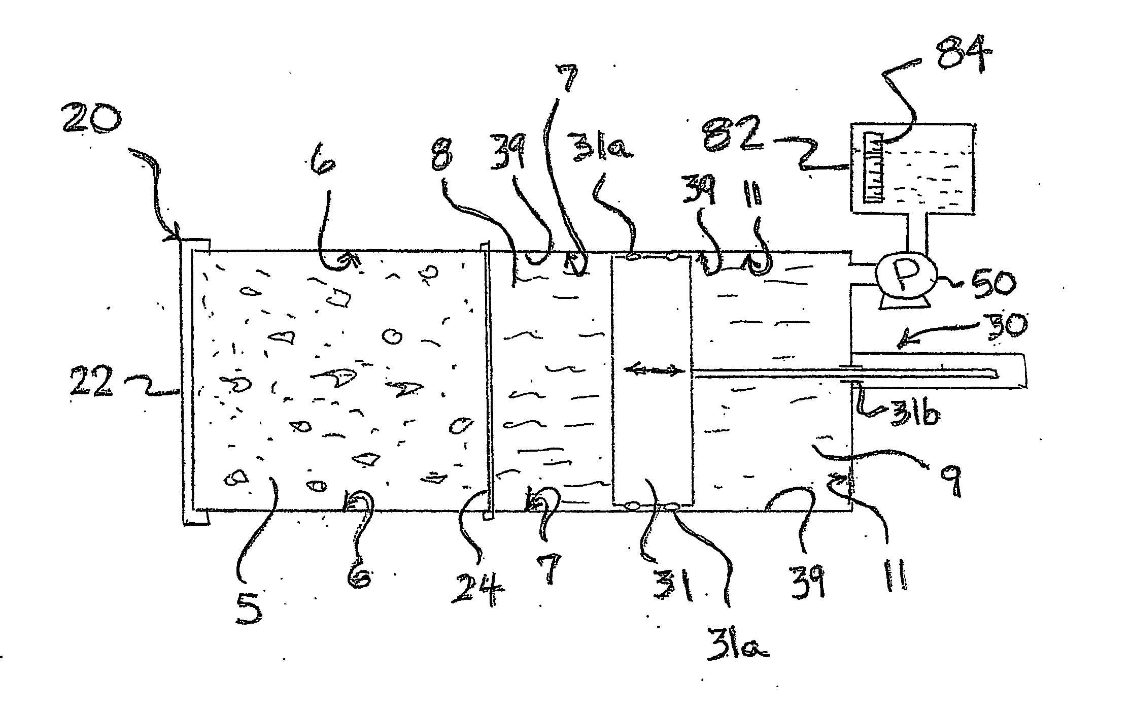
[0040] With reference to FIG. 1, a simplified schematic view of a pressure vessel assembly housing 20 is shown with a fresh sample 5 filling a sample containing portion 6 with its inner surface covered securely by a flexible barrier seal 24 and the housing 20 closed by threaded end cap 22. A first pressurized chamber 7 contains pressurized liquid 8, which is preferably water. All entrained air has been removed from the sample 5 and air has been excluded from the liquid in the first chamber 7. A piston 31 with seals 31a, which can be O-rings, is movably positioned in a bore section 39 of housing 20. A second pressurizing chamber 11 is formed in the end of housing 20 and contains a pressurizing fluid 9 that is in fluid communication with external reservoir 82. A pump 50 is activated to maintain the desired pressure on the preferably incompressible pressurizing fluid in second chamber 11.
[0041] With continuing reference to FIG. 1, a sensor assembly 30, includes a direct mechanical con...
PUM
 Abstract
Description
Claims
Application Information