Link plate for a plate-link chain

a technology of plate-link chain and link plate, which is applied in the direction of driving chains, belts/chains/gearrings, chain elements, etc., can solve the problems of more severe loading and damage to the link plate, and achieve the effect of increasing the anti-turning protection of the rocker members in the openings of the link plate, increasing fatigue strength, and increasing tractive for

Inactive Publication Date: 2007-06-21
LUK LAMELLEN & KUPPLUNGSBAU BETEILIGUNGS KG
View PDF7 Cites 8 Cited by
  • Summary
  • Abstract
  • Description
  • Claims
  • Application Information

AI Technical Summary

Benefits of technology

[0030] By having the smallest radius of curvature located substantially in the middle of the arc length, the greatest curvature falls outside of the respective end region of the contact surfaces. That results in the rocker members becoming stiffer than in an arrangement where the smallest radius of curvature is in the region of the respective ends of the contact surfaces, and hence they deflect less. With the rocker members deflecting less, the tractive force is distributed more evenly over all of ...

Problems solved by technology

It is also known that such link plates, as well as plate-link chains incorporating them, are limited in their ability to transmit power, and that the possibility thus exists that a link plate will be damaged, by power peaks for example, and will fail.
Failure can be manifested in breaking of the link plate, wherein starting from that broken link plate a failure or breakin...

Method used


Image

  • Link plate for a plate-link chain
  • Link plate for a plate-link chain
  • Link plate for a plate-link chain

Examples


first embodiment

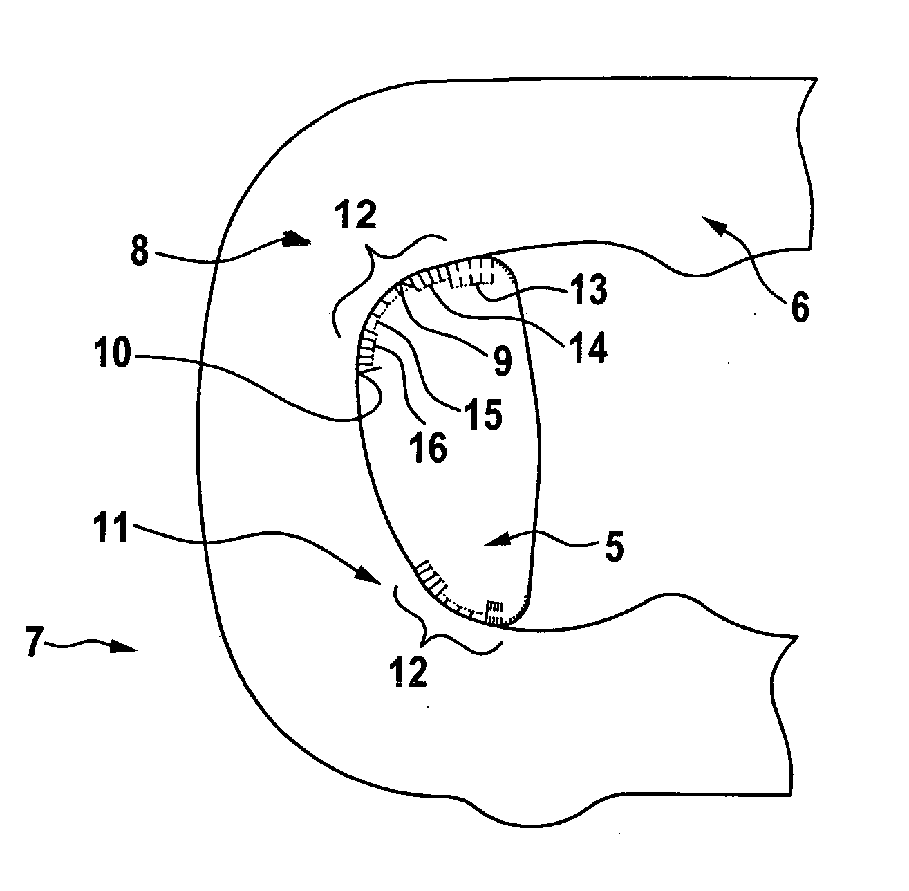
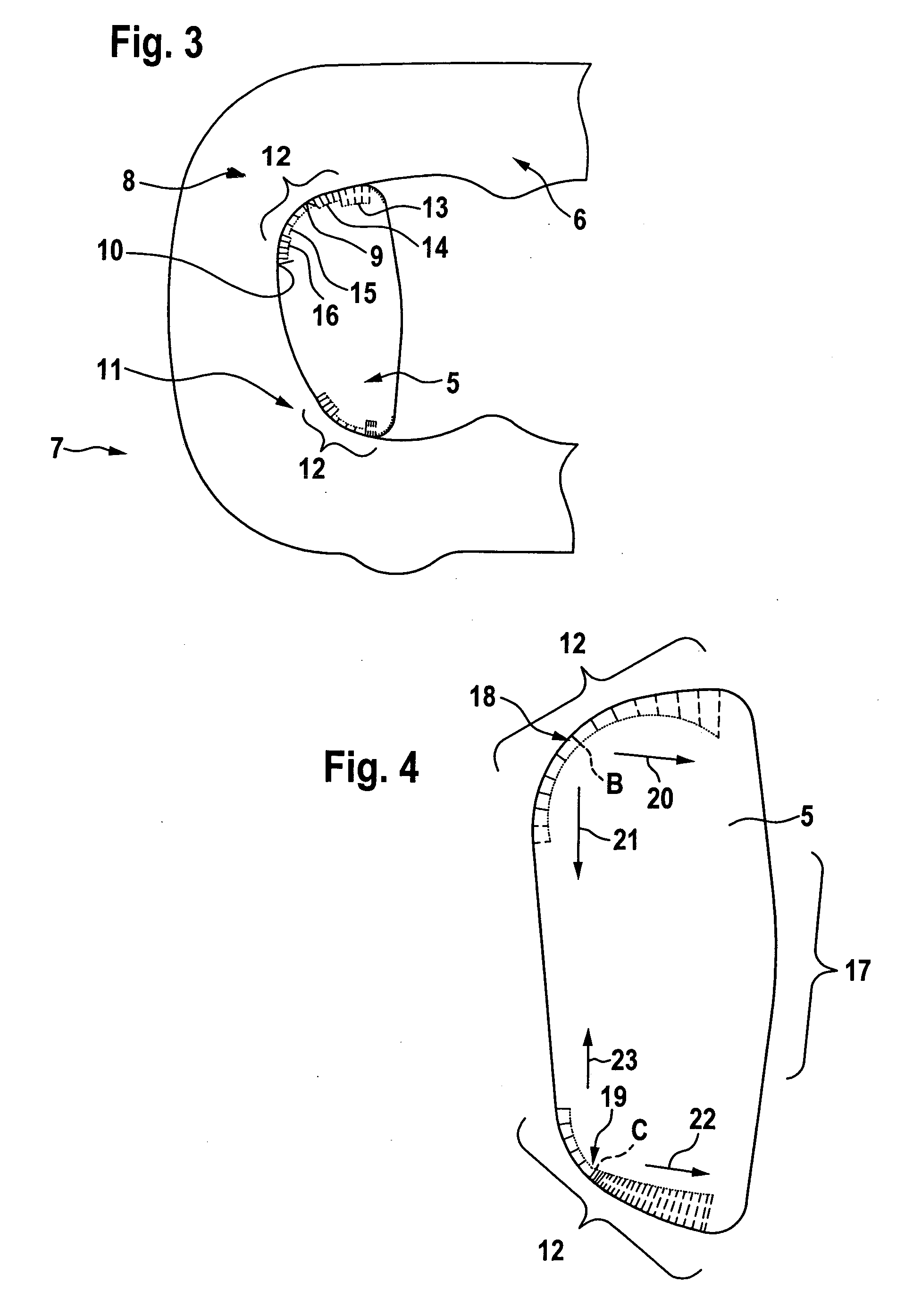
[0043]FIG. 3 of the drawings shows an enlarged representation of a rocker member 5 and a link plate 6 of a plate-link chain 7 according to the present invention.

[0044] As can be seen in FIG. 3, there are two contact surface regions 8 and 11 between rocker member 5 and link plate 6, contact surface region 8 being formed by a contact surface 9 on rocker member 5 and a contact surface 10 on the link plate 6. In a similar manner, contact surface region 11 is composed of a contact surface on rocker member 5 and a complementarily-formed contact surface on link plate 6.

[0045] Rocker member 5 and link plate 6 are in contact with each other at contact surface 9 and contact surface 10 to transmit force. Since link plate 6 has a certain thickness in the direction transverse to the drawing plane of FIG. 3, and a plurality of those link plates lying side by side are in contact with the same rocker member 5, the tractive force transmitted by plate-link chain 7 is distributed over the individual ...

second embodiment

[0048]FIG. 4 of the drawings shows a rocker member 5 of a plate-link chain according to the present invention, wherein that rocker member is a rocker member of a plate-link chain for a belt-driven conical-pulley transmission.

[0049] On rocker member 5, reference numeral 17 designates the roller surface with which rocker member 5 rolls against the opposing rocker member (again, a pair of rocker members is involved), the basic configuration being visible on the basis of FIG. 2 of the drawing. Rocker member 5, in turn, has two contact surfaces 18, 19, which are positioned against complementarily-formed contact surfaces of a link plate (not shown). The upper contact surface 18 has a point designated as B at which the maximum curvature is located, i.e., where the radius of curvature, which is again shown perpendicular to contact surface 18 by way of explanation, is at its minimum. Starting from point B the radius of curvature increases in both directions, so that the curvature becomes con...


PUM


Abstract

A link plate and a plate-link chain for a vehicle drive. A large number of link plates are articulatingly connected with each other by rocker members, wherein the rocker members run transversely to the longitudinal direction of the plate-link chain. Contact surfaces are formed on the rocker members and on the link plates, along which contact surfaces the rocker members and link plates are in contact with each other to transmit force. The respective contact surfaces are each defined by different adjacent curved regions of different radii of curvature that are selected to minimize stress spikes on the link plate contact surfaces, and particular size relationships between the link plates and the rocker members are identified.

Description

BACKGROUND OF THE INVENTION [0001] 1. Field of the Invention [0002] The present invention relates to a link plate for a plate-link chain for use in a drive system. The invention also relates to a plate-link chain that is made using link plates according to the invention, as well as to a chain drive that incorporates such a plate-link chain and a vehicle that includes such a chain drive. [0003] 2. Description of the Related Art [0004] Both link plates and plate-link chains of the type referred to above are known in many forms from the known state of the art, as is explained hereinafter. It is also known that such link plates, as well as plate-link chains incorporating them, are limited in their ability to transmit power, and that the possibility thus exists that a link plate will be damaged, by power peaks for example, and will fail. Failure can be manifested in breaking of the link plate, wherein starting from that broken link plate a failure or breaking of the entire plate-link cha...

Claims


Application Information

Patent Timeline
IPC IPC(8): F16G13/04
CPCF16G5/18F16G13/04
Inventor VORNEHM, MARTINPICHURA, MICHAELSIMONOV, ANTONTRILLER, ANDREASJUNIG, MARCUSISPOLATOVA, OLGA
Owner LUK LAMELLEN & KUPPLUNGSBAU BETEILIGUNGS KG
Why Eureka
Try Eureka