Patient breathing circuit

a breathing circuit and patient technology, applied in the direction of valve details, valve arrangements, inhalators, etc., can solve the problems of shortening the space between the patient and the y-piece, and achieve the effect of reducing the number of connections in the breathing circuit, reducing the risk of leakage, and improving patient safety

Inactive Publication Date: 2007-08-23
GENERAL ELECTRIC CO
View PDF7 Cites 14 Cited by
  • Summary
  • Abstract
  • Description
  • Claims
  • Application Information

AI Technical Summary

Benefits of technology

[0007]An advantage of the invention over the prior art is that the amount of connections in breathing circuit is diminished decreasing the risk for leaks and hence ensuring better patient safety. Additionally, the space between the patient and the Y-piece becomes shorter since the spirometry sensor is integrated with the Y-piece diminishing the volume of dead space. By dead space is meant the quantity of exhaled gases, which return to the patient. The invention is also flexible, i.e. the invention can be used in connection with different constructions. In other words the invention can quite well be used in both coaxial and two limb patient breathing circuits. The expression Y-piece thus includes also connector for coaxially connecting inhalation and exhalation tubes.

Problems solved by technology

Additionally, the space between the patient and the Y-piece becomes shorter since the spirometry sensor is integrated with the Y-piece diminishing the volume of dead space.

Method used


Image

  • Patient breathing circuit
  • Patient breathing circuit
  • Patient breathing circuit

Examples


Embodiment Construction

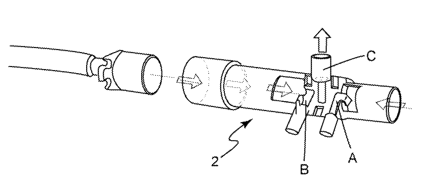
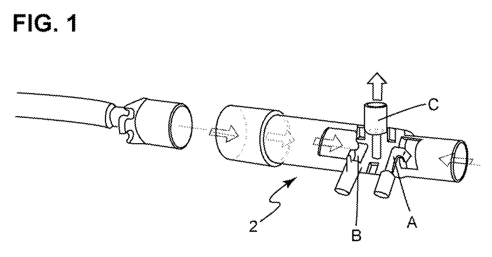
[0017]FIG. 1 shows a prior art flow measuring and gas sampling detector, i.e. the spirometry sensor described in U.S. Pat. Nos. 5,088,332 and 5,111,827. This known sensor called the D-lite™ patient spirometry™ sensor is currently in use. A and B represent ports for pressure sensing tubes and C for gas analysis, as will be described below.

[0018]As told above the D-lite™ patient spirometry™ sensor in FIG. 1 incorporates three ports: two for pressure sensing (A and B) and one for sidestream gas analysis (C). The velocity of gas flow is obtained when the dynamic pressure is measured by the two hollow tubes (A and B). On inspiration, gas moves for example from an anaesthesia machine to the patient (by point A), which measures the total pressure, and the same time the pressure at tube B is measured as the static pressure. The static pressure at B is subtracted from the total pressure at A to give the dynamic pressure. Dynamic pressure is proportional to the velocity of gas flow. “D-Lite™ ...


PUM


Abstract

The invention relates to patient breathing circuit for use in anaesthesia or respiratory care, the patient circuit comprising a gas source for creating gas mixture for patient breathing and circulating arrangement for delivering the gas mixture to the patient. The circulating arrangement comprising inspiration (9) and expiration tubes (8) through which gases flow to the patient and from the patient, the inspiration and expiration tubes (8,9) having machine ends and patient ends and the tubes (8,9) being provided with a Y-piece (12) at the patient end of the tubes enabling the flow of gases from the inspiration tube (9) to the patient (1) and from the patient (1) to the expiration tube (8). The Y-piece (12) is provided with a flow measuring sensor (2) having pressure lines (3) connected to the measuring device. The pressure lines (3) are arranged to run inside of an outer wall surface of the flow measuring sensor (2).

Description

BACKGROUND OF INVENTION[0001]The invention relates to a patient breathing circuit for use in anaesthesia or respiratory care, the patient circuit comprising a gas source for creating gas mixture for patient breathing and circulating arrangement for delivering the gas mixture to the patient, the circulating arrangement comprising inspiration and expiration tubes through which gases flow to the patient and from the patient, the inspiration and expiration tubes having machine ends and patient ends, the tubes being provided with a Y-piece at the patient end of the tubes enabling the flow of gases from the inspiration tube to the patient and from the patient to the expiration tube, the Y-piece being provided with a flow measuring sensor having pressure lines connected to the measuring device.[0002]Monitoring of ventilation is often difficult due to the limitations of available technology and monitoring equipment. Most devices utilized for measuring and monitoring ventilation are located ...

Claims


Application Information

Patent Timeline
Patent Type & Authority Applications(United States)
IPC IPC(8): A61M15/00A61M16/00
CPCA61M16/08A61M16/085A61M2016/0036A61M16/0858
Inventor LAURILA, SANTTUHOLOPAINEN, TIMORANTA, JANNETOMMINEN, ANNE
Owner GENERAL ELECTRIC CO
Why Eureka
Try Eureka