Thermal Limited Backlight Driver

a backlight driver and thermal limitation technology, applied in pulse manipulation, pulse technique, instruments, etc., can solve the problems of reducing the maximum luminance, limiting the range of the pwm duty cycle, and requiring a large plurality of power sources, so as to reduce the duty cycle of pulse width modulation functionality and reduce thermal stress

Inactive Publication Date: 2007-08-23
POLARIS POWERLED TECH LLC
View PDF16 Cites 27 Cited by
  • Summary
  • Abstract
  • Description
  • Claims
  • Application Information

AI Technical Summary

Benefits of technology

[0012]Accordingly, it is a principal object of the present invention to overcome the disadvantages of prior art. This is provided in the present invention by a backlighting system exhibiting a plurality of LED strings, a plurality of current limiters each in series with a particular one of the plurality of LED strings, and a pulse width modulation functionality. The control circuitry is operative to monitor at least one thermal condition responsive to the plurality of current limiters, and in the event of a predetermined thermal condition, reduce the thermal stress by reducing the duty cycle of at least one of the plurality of LED strings.
[0013]The invention provides for a system for powering and controlling an LED backlight, the system comprising: a control circuitry; a plurality of LED strings; a pulse width modulation functionality associated with the control circuitry and arranged to pulse width modulate a current flow through each of the plurality of LED strings; and a plurality of current limiters responsive to the control circuitry, each of the plurality of current limiters being associated with a particular one of the plurality of LED strings and operative to limit current flow of the pulse width modulated current there-through, the control circuitry being operative in the event of a thermal condition of one of the plurality of current limiters to reduce a duty cycle of the pulse width modulation functionality of the current flow through the one of the plurality of current limiters.

Problems solved by technology

There is however a limit to the range of the PWM duty cycle and unfortunately when it has been reached, the maximum luminance begins to decline.
Such a large plurality of power sources effectively minimizes excess power dissipation however the requirement for a large plurality of power sources is costly.
Unfortunately, since as indicated above different LED strings of the same color may exhibit different voltage drops, such a solution further requires an active element in series with each LED string to compensate for the different voltage drops so as to ensure an essentially equal current through each of the LED strings of the same color.
Unfortunately, the dissipative elements limit the range of operation of the controller chip, since the dissipative elements are a significant source of heat.
Placing the dissipative elements external of the controller chip solves the problem of heat but unfortunately results in a higher cost and footprint and is thus less than optimal.
Utilizing a single fixed voltage power source for each color thus results in excess power dissipation, as the power source is set to supply a sufficient voltage for all the LED strings over their operational life, which must be dissipated for LED strings exhibiting a lower voltage drop.

Method used


Image

  • Thermal Limited Backlight Driver
  • Thermal Limited Backlight Driver
  • Thermal Limited Backlight Driver

Examples


Embodiment Construction

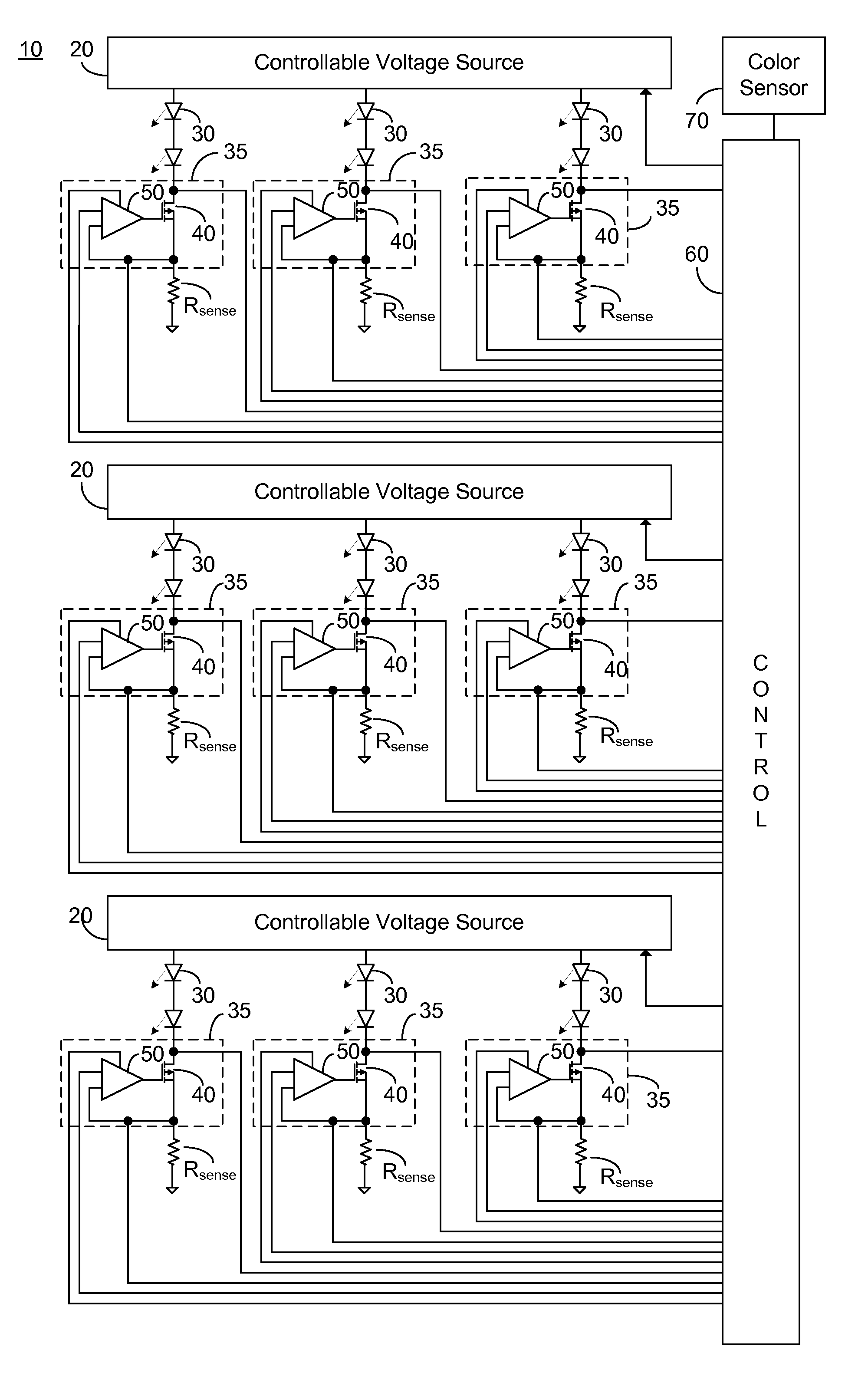
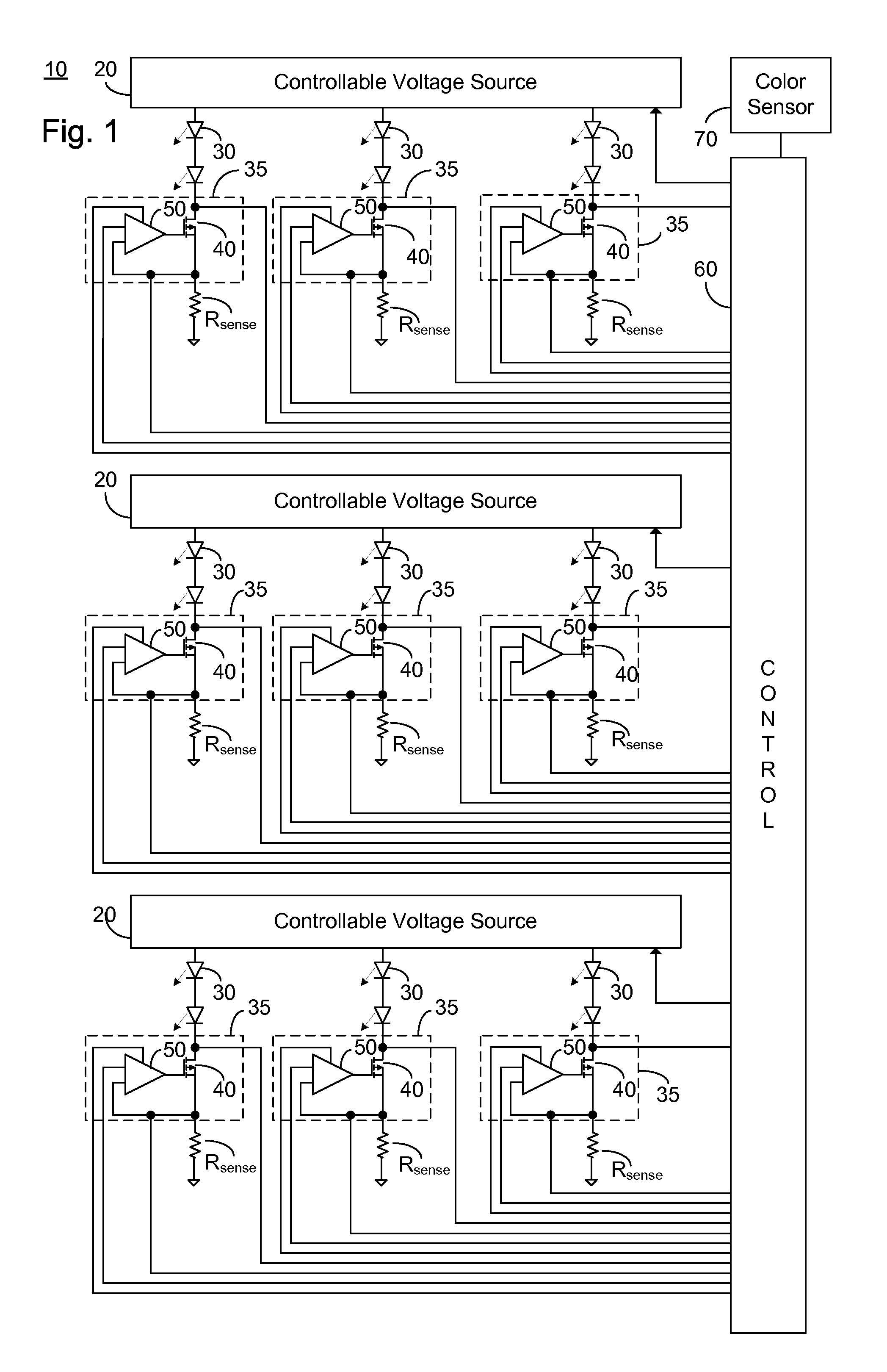
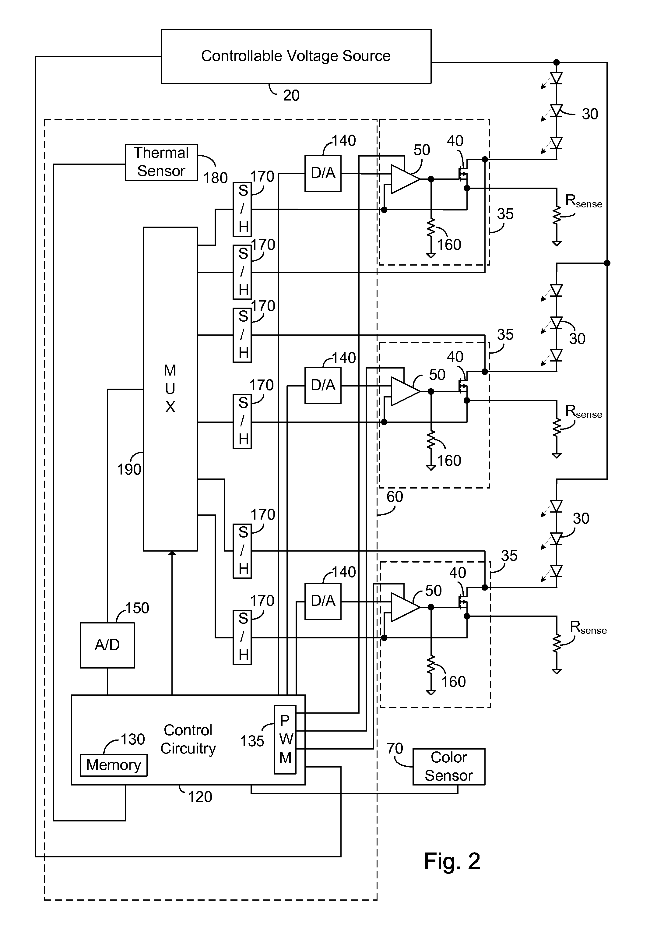
[0028]The present embodiments enable a backlighting system exhibiting a plurality of LED strings, a plurality of current limiters each in series with a particular one of the plurality of LED strings, and a pulse width modulation functionality. The control circuitry is operative to monitor at least one thermal condition responsive to the plurality of current limiters, and in the event of a predetermined thermal condition, reduce the thermal stress by reducing the duty cycle of at least one of the plurality of LED strings.

[0029]Before explaining at least one embodiment of the invention in detail, it is to be understood that the invention is not limited in its application to the details of construction and the arrangement of the components set forth in the following description or illustrated in the drawings. The invention is applicable to other embodiments or of being practiced or carried out in various ways. Also, it is to be understood that the phraseology and terminology employed h...


PUM


Abstract

A system for powering and controlling an LED backlight, the system comprising: a control circuitry; a plurality of LED strings; a pulse width modulation functionality associated with the control circuitry and arranged to pulse width modulate a current flow through each of the plurality of LED strings; and a plurality of current limiters responsive to the control circuitry, each of the plurality of current limiters being associated with a particular one of the plurality of LED strings and operative to limit current flow of the pulse width modulated current there-through, the control circuitry being operative in the event of a thermal condition of one of the plurality of current limiters to reduce a duty cycle of the pulse width modulation functionality of the current flow through the one of the plurality of current limiters.

Description

CROSS-REFERENCE TO RELATED APPLICATIONS[0001]This application claims priority from: U.S. Provisional Patent Application Ser. No. 60 / 775,787 filed Feb. 23, 2006 entitled “Thermal Limited Backlight Driver”; U.S. Provisional Patent Application Ser. No. 60 / 803,366 filed May 28, 2006 entitled “Voltage Controlled Backlight Driver”; and U.S. Provisional Patent Application Ser. No. 60 / 868,675 filed Dec. 5, 2006 entitled “Voltage Controlled Backlight Driver”, the entire contents of each of which are incorporated herein by reference.BACKGROUND OF THE INVENTION[0002]The present invention relates to the field of light emitting diode based lighting and more particularly to a system for powering and controlling a plurality of LED strings having a controllable power source.[0003]Light emitting diodes (LEDs) and in particular high intensity and medium intensity LED strings are rapidly coming into wide use for lighting applications. LEDs with an overall high luminance are useful in a number of appli...

Claims


Application Information

Patent Timeline
Patent Type & Authority Applications(United States)
IPC IPC(8): G09G3/32H05B44/00
CPCG09G3/006H05B33/0893G09G3/342G09G2320/0233G09G2320/041G09G2320/064G09G2320/0666G09G2330/021G09G2330/045G09G2330/08G09G2330/12G09G2360/14H05B33/0827H05B33/0869G09G3/3413H05B45/58H05B45/22H05B45/46
Inventor KORCHARZ, DRORPEKER, ARKADIY
Owner POLARIS POWERLED TECH LLC
Why Eureka
Try Eureka