Automatic Lathe

a technology of automatic lathes and lathes, which is applied in the direction of turning machine accessories, auxiliaries equipment, manufacturing tools, etc., can solve the problems of unsuitable automatic lathes for products requiring more accurate machining, inability to machine rod materials shorter than this distance, and remaining materials, so as to reduce equipment costs and machining costs, and facilitate fitting/removing. , the effect of high accuracy

Inactive Publication Date: 2007-10-04
CITIZEN WATCH CO LTD
View PDF13 Cites 12 Cited by
  • Summary
  • Abstract
  • Description
  • Claims
  • Application Information

AI Technical Summary

Benefits of technology

[0032] The configuration of the present invention is as described above, so that the guide bush is easily fitted / removed, and one automatic lathe can be switched to rapidly adapt to the machining with the guide bush and the machining without the guide bush, thereby allowing reductions in equipment cost and machining cost. Further, when the guide bush is used, even an elongated product can be continuously machined with relatively high accuracy. When the guide bush is not used, the spindle is positioned and fixed at the specified position on the guide bush support table, or the guide member and the tip of the spindle are fixed by the attachment, thereby allowing a rigid spindle configuration. Therefore, a relatively short product can be highly accurately machined, and the machining can be carried out with a heavy cutting load.

Problems solved by technology

However, in spite of the advantage described above, the automatic lathe equipped with the guide bush has a problem that there is a gap, which is small, between the guide bush and the rod material, and the rod material moves due to this gap, which makes the automatic lathe unsuitable to machine products requiring more accurate machining.
Furthermore, there is a problem that, due to a condition that the dimension of the rod material be longer than at least a distance between a grip position of the chuck at the forward end of the spindle and a machining position in the vicinity of the guide bush, it is not possible to machine a rod material shorter than this distance.
Moreover, there is a problem that if a long rod material is machined, a material between the grip position and the machining position results in a remaining material.
Thus, the automatic lathe equipped with the guide bush has a problem of increased equipment cost and machining cost because its use is limited to the machining of the rod materials having a length equal to or longer than a certain length.
Thus, a certain length of the tip of the spindle protrudes from a tool post, but the part protruding from the tool post is not supported.
This leads to a problem that the tip of the spindle bends to result in a decreased machining accuracy when machining a relatively short product requiring high machining accuracy which needs to be machined without using the guide bush and when machining is carried out with a heavy cutting load.
However, even the technique described in this document can not solve the above-mentioned problem of producing a remaining material.
Moreover, there are needed a mechanism to open / close the chuck of the guide bush, and a mechanism to open / close the spindle chuck, so that the configuration of the automatic lathe is complicated and the length of the spindle is increased, leading to another problem that the overall length of a machine is increased.

Method used


Image

  • Automatic Lathe
  • Automatic Lathe
  • Automatic Lathe

Examples


Embodiment Construction

[0042] One preferred embodiment of the present invention will hereinafter be described in detail with reference to the drawings.

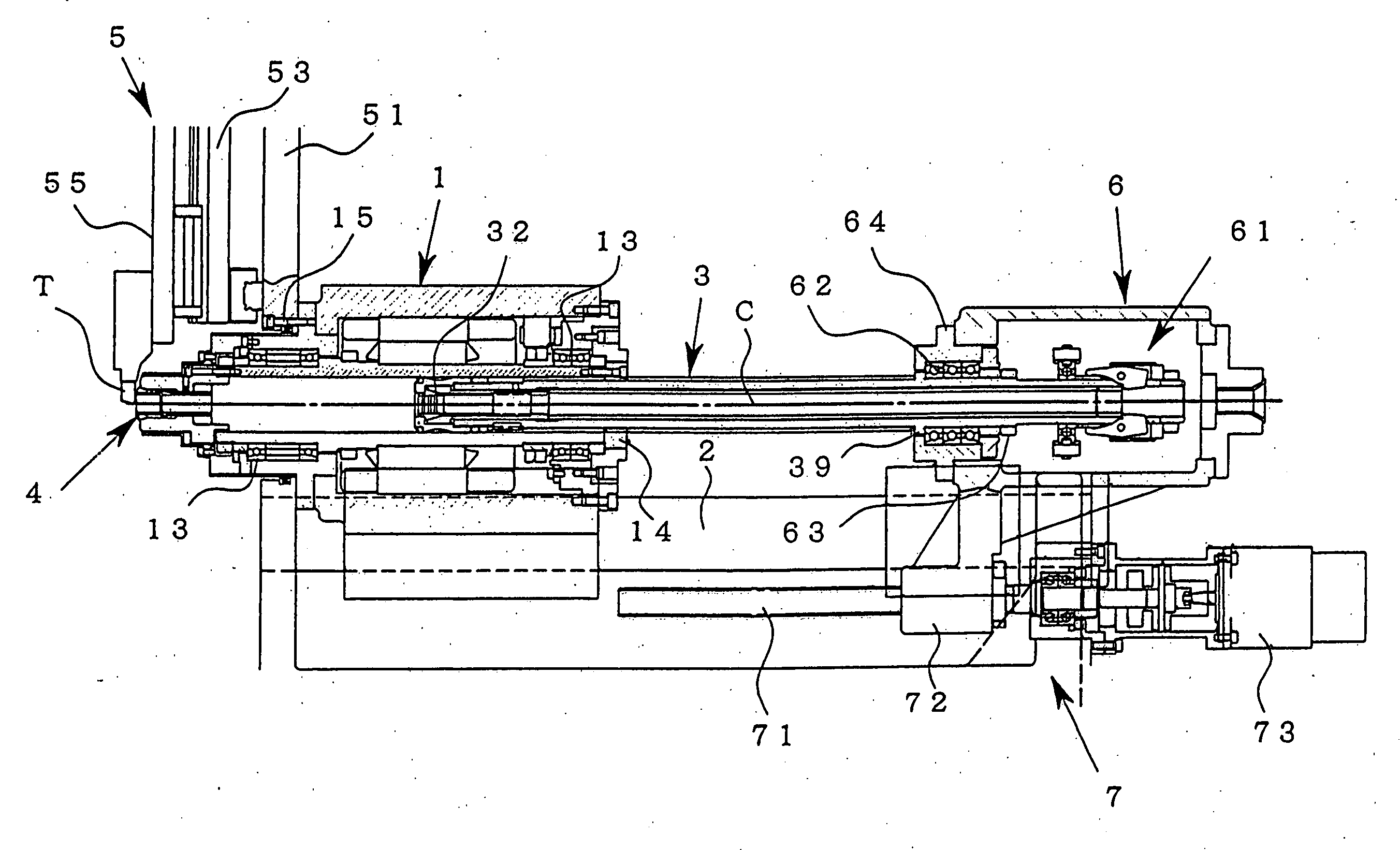
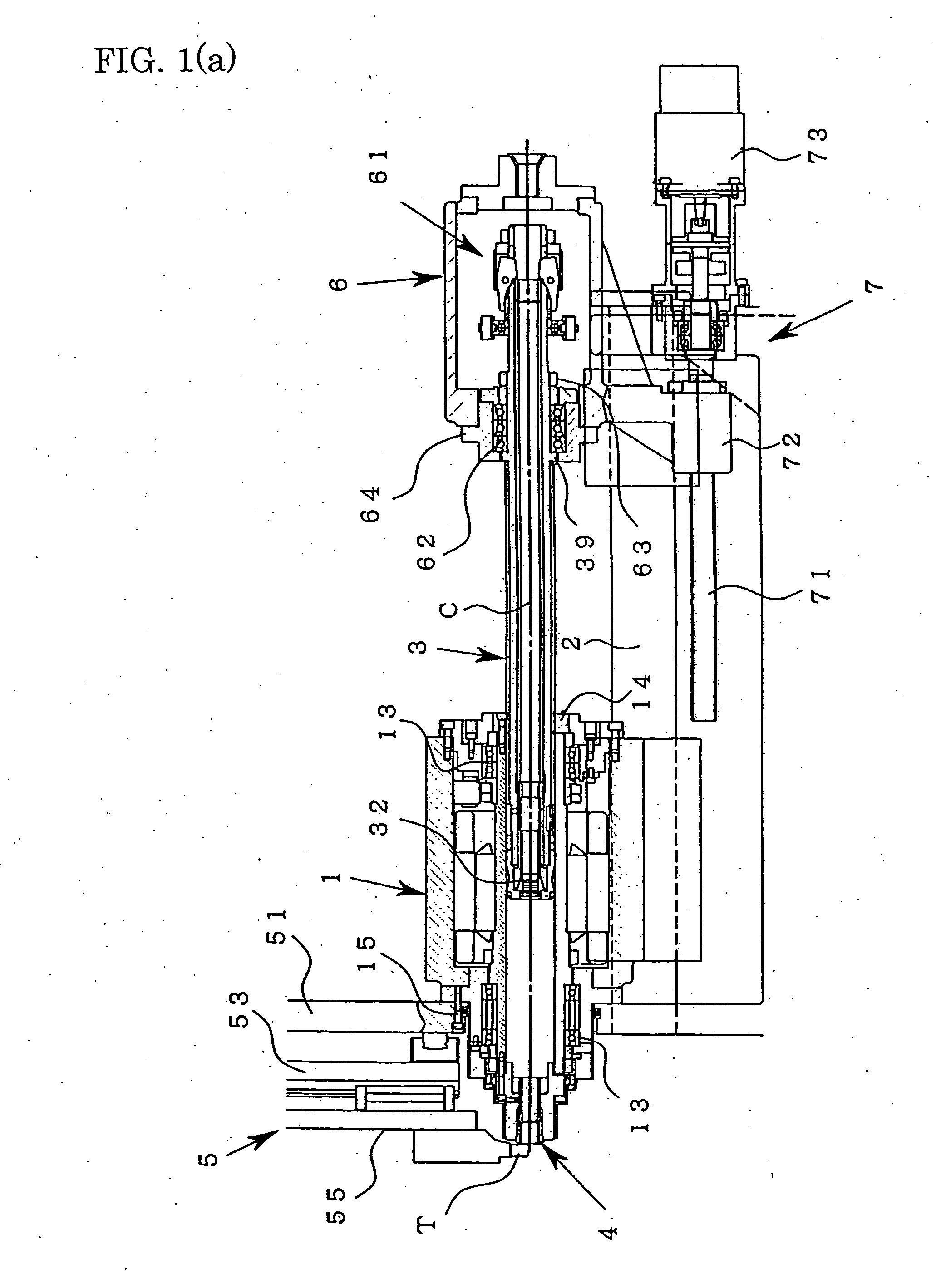
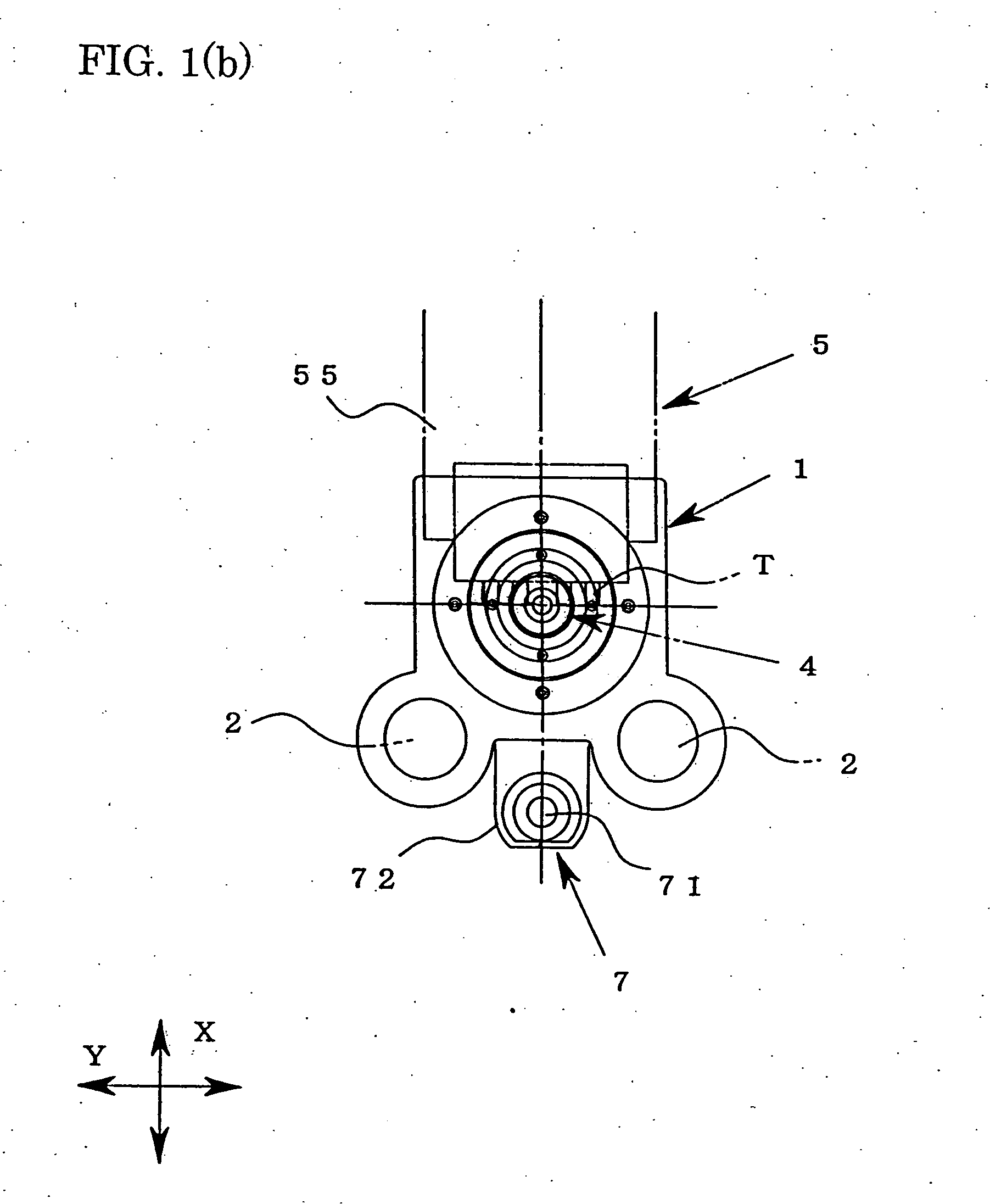
[0043]FIG. 1 concerns one embodiment of an automatic lathe of the present invention, wherein FIG. 1(a) is a sectional view explaining the configuration of essential parts including a guide bush support table and a head stock, and FIG. 1(b) is a front view of the guide bush support table in FIG. 1(a).

[0044] It is to be noted that in the following description, “front”, when referred to, indicates a front end side of a spindle provided with a chuck which grips a rod material, that is, the left side in FIG. 1(a), while “rear”, when referred to, indicates a rear end side of the spindle, that is, the right side in FIG. 1(a).

[0045] As shown in FIG. 1(a), the automatic lathe in this embodiment has: a slide guide 2 provided on an unshown bed; a head stock 6 which freely moves in forward and backward directions on the slide guide 2; a guide bush support table 1 di...


PUM

PropertyMeasurementUnit
widthaaaaaaaaaa
thermal expansionaaaaaaaaaa
dimensionaaaaaaaaaa

Abstract

An automatic lathe is provided which is capable of rapidly and easily switching between machining of a material with a guide bush and machining of the material without the guide bush.
The automatic lathe has a guide bush support table (1) disposed closer to a tip side of a spindle (3) than a head stock (6); support table fixing means (15) for fixing the guide bush support table (1); a guide member (12) rotatably installed on the guide bush support table (1) so as not to move forward and backward; a guide bush (4) detachably fitted to the tip of the guide member (12); driving means (11) for rotating the guide bush (4); rotation transmission means (14a) and (31) for transmitting the rotation of the guide member (12) to the spindle (3); spindle moving means (7) for moving the spindle (3) forward and backward within the guide member (12); and spindle fixing means (17), (36) and (38) for positioning and fixing the spindle (3) at a specified position on the guide bush support table (1) when the guide bush (4) is removed from the guide member (12).

Description

TECHNICAL FIELD [0001] The present invention relates to an automatic lathe having a spindle and a tool post capable of relative movement, and the automatic lathe machines a material gripped by a chuck at the tip of the spindle by use of a tool installed on the tool post. BACKGROUND ART [0002] In some known machine tools such as a numerically controlled (NC) automatic lathe capable of implementing various kinds of automatic lathe-turning machining (hereinafter generically called an automatic lathe), a guide bush is provided in the vicinity of a position where machining is performed with a tool, and the tip of a long rod-like material (hereinafter referred to as a rod material) gripped by a chuck at the tip of a spindle is supported by the guide bush and thus machined (e.g., refer to Japanese Patent Publication Laid-open No. 4-115804). [0003] In the machining of the rod material using the guide bush, a part to be machined at the tip of the rod material is supported so as not to cause ...

Claims


Application Information

Patent Timeline
Patent Type & Authority Applications(United States)
IPC IPC(8): B23B13/02B23B25/00B23Q1/76
CPCB23B3/161B23B7/06B23B13/02B23B25/00Y10T82/25Y10T82/2572Y10T82/26Y10T82/2504Y10T82/2552B23Q1/763B23B13/00
Inventor ASAHARA, NORIYUKITAKAHASHI, TORUHIRAKAWA, YOSHIAKIANDO, YOSUKESUZUKI, TOSHIYUKITSUYUSAKI, UMEO
Owner CITIZEN WATCH CO LTD
Why Eureka
Try Eureka