Vessel treatment devices

a treatment device and valve technology, applied in the field of valve treatment devices and methods, can solve the problems of difficult operation and access to the site, inaccurate positioning within the vessel, and difficult to perform multiple insertions and retractions

a treatment device and valve technology, applied in the field of valve treatment devices and methods, can solve the problems of difficult operation and access to the site, inaccurate positioning within the vessel, and difficult to perform multiple insertions and retractions

US20080033525A1Active Publication Date: 2008-02-07Y MED

Image

  • Vessel treatment devices
  • Vessel treatment devices
  • Vessel treatment devices

Examples


first embodiment

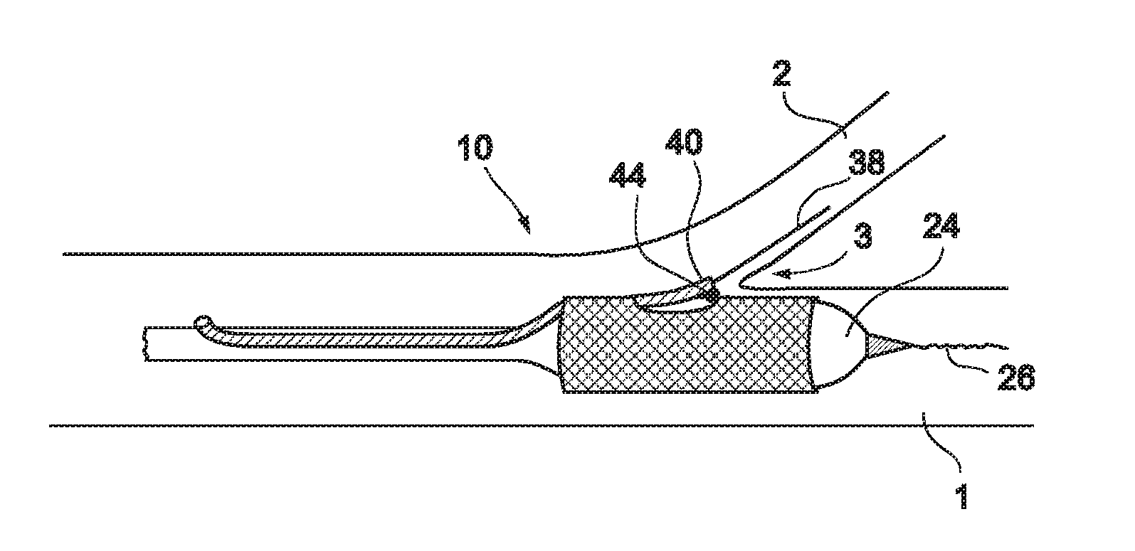
[0065] In a first embodiment, a stent delivery system 10 is designed to be delivered at a Type 1, Type 2 or Type 4 bifurcation lesion, as illustrated in FIGS. 29a, 29b and 29d, respectively. In these types of bifurcation lesions, the plaque 4 is at least partially located within the main vessel in the vicinity of bifurcation point 3, and may also be located within branch vessel 2.

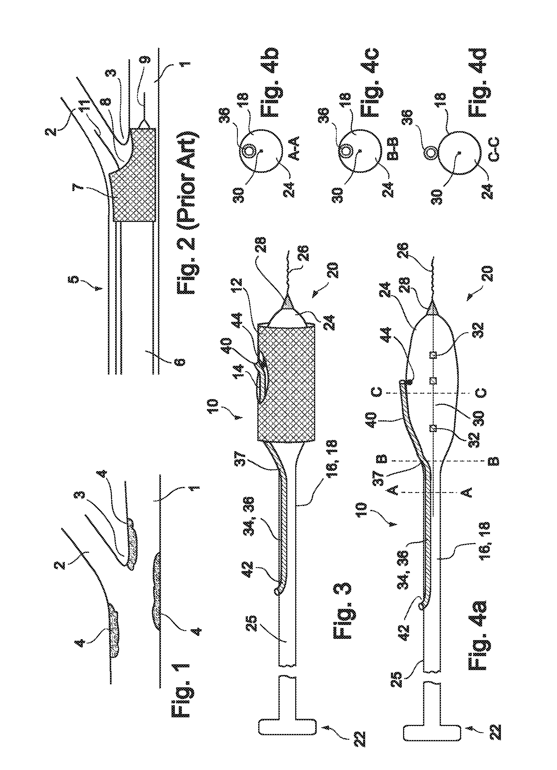
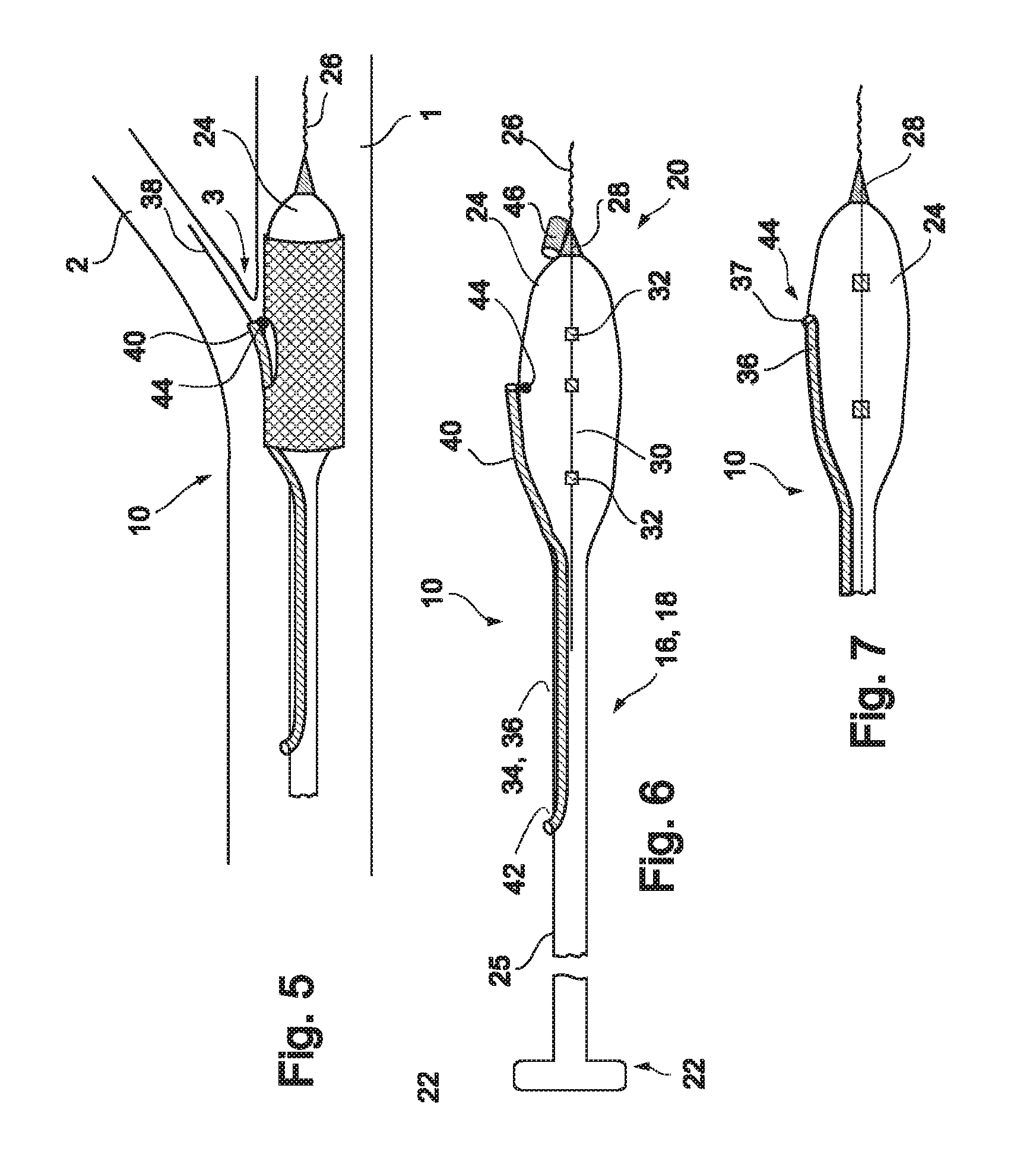
[0066] Reference is now made to FIG. 3 and FIGS. 4a-d, which are illustrations of a bifurcation stent delivery system 10, shown with and without a stent respectively. System 10 includes a main elongated element 16, and an auxiliary elongated element 34 aligned with main elongated element 16. In a preferred embodiment, auxiliary elongated element 34 is positioned within main elongated element 16 proximal to an exit point 37 and alongside main elongated element 16 distal to exit point 37, as depicted in FIG. 3. In an alternative embodiment, auxiliary elongated element 34 is positioned alongside main elongated...

second embodiment

[0086] In a second embodiment, a stent delivery system 110 is designed to be delivered at a Type 4A or 4B bifurcation lesion as illustrated in FIGS. 29e and 29f. In a Type 4A lesion, plaque 4 is located in branch vessel 2, at or near bifurcation 3. In a Type 4B lesion, plaque 4 is located in main vessel 1 distal to the point of bifurcation 3. One example of such a location is the coronary artery, where blockage of, for example, the left anterior descending (LAD) artery is to be avoided while providing coverage to the plaque within the coronary artery. Other examples include renal arteries, the left main coronary artery, vein grafts, and others.

[0087] Reference is now made to FIGS. 11a-c, which are illustrations of different embodiments of a system 110 for delivery of a stent at a Type 4A or Type 4B bifurcation lesion. System 110 may be designed with a fixed wire, as shown in FIG. 11a, as on over-the-wire system, as shown in FIG. 11b, or as a rapid exchange system, as shown in FIG. 1...


PUM


Abstract

A catheter system for treating lesions is provided. The system is suitable for treatment of bifurcation lesions, has a low profile and provides substantially predictable translational and rotational positioning. In one embodiment, the system includes a fixed wire balloon catheter and a partially attached guidewire lumen, wherein the guidewire lumen is attached to the catheter at a crotch point. The location of the crotch point is predetermined so as to provide substantially predictable positioning. Several embodiments of the system are described for various types of lesions and vessel configurations.

Description

CROSS-REFERENCE TO RELATED APPLICATIONS [0001] This application is a continuation-in-part application of U.S. patent application Ser. No. 11 / 240,631, filed on Oct. 3, 2005, which is a continuation-in-part application of U.S. patent application Ser. No. 11 / 070,294, filed on Mar. 3, 2005, which is a continuation-in-part application of U.S. patent application Ser. No. 10 / 899,034, filed on Jul. 27, 2004, which claims the benefit of U.S. Provisional Application No. 60 / 549,554, filed on Mar. 4, 2004, all of which are incorporated herein by reference in their entireties.FIELD AND BACKGROUND OF THE INVENTION [0002] The present invention relates to vessel treatment devices and methods and, more particularly, to catheter systems having low profiles and predictable positioning capabilities, both rotationally and translationally. [0003] Several problems are associated with known prior art stent delivery devices, particularly ones which are suitable for treating bifurcation lesions. First, they ...

Claims


Application Information

Patent Timeline
07 Feb 2008
Publication
US20080033525A1
IPC
A61F2/06; A61F2/82
CPC
A61B17/12022; A61M2025/1056; A61B17/12136; A61B17/1214; A61B2017/1205; A61B2017/22067; A61B2017/22068; A61B2017/22069
Inventors
SHAKED, YOAV; SOLAR, RONALD J.