Dental flosser with bendable head

Active Publication Date: 2008-03-20
RANIR LLC
View PDF7 Cites 11 Cited by
  • Summary
  • Abstract
  • Description
  • Claims
  • Application Information

AI Technical Summary

Benefits of technology

[0016] The bent orientation has a further significant advantage, in that a flosser of this overall shape is easier and / or more effective for some persons to use, especially between the back teeth.
[0021] 2. In a bendable head flosser the latch may permanently or releasably maintain the flosser head bent in the inclined position.

Problems solved by technology

Prior to such stretching, the new device is generally flat and unusable, with a handle part and a flosser part including floss that is slack, namely, not taut or perfectly linear.

Method used


Image

  • Dental flosser with bendable head
  • Dental flosser with bendable head
  • Dental flosser with bendable head

Examples


first embodiment

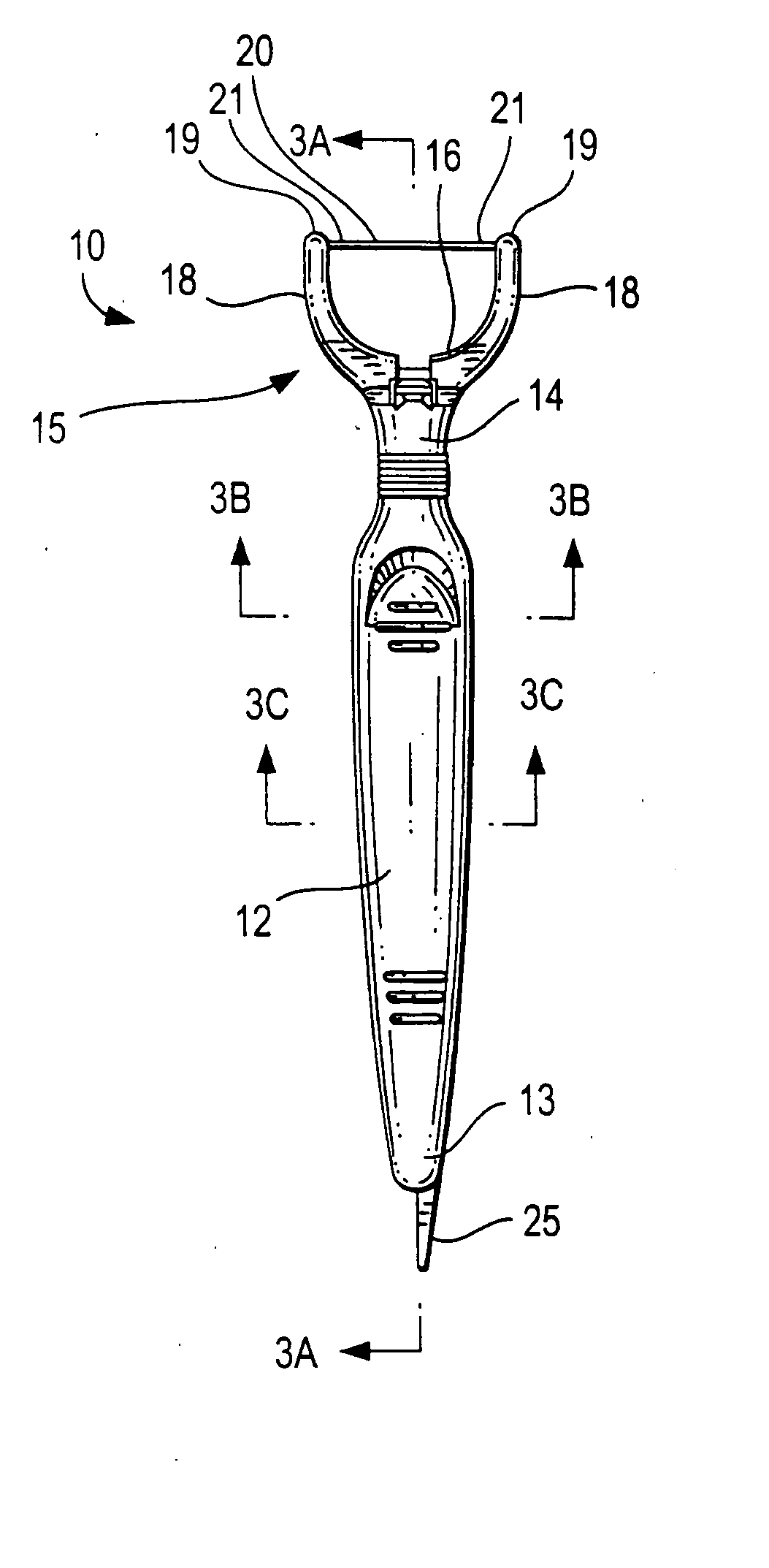
[0060] FIG. 1 one shows the new dental flosser 10 having a handle 12 with proximal end 13 and distal end 14, and a flosser head part 15 having a base 16 and a pair of spaced apart arms 18, each arm having a distal tip end 19. A strand of dental floss 20 extends between the tips of the arms with the ends of the floss 21 secured in the ends 19 of the arms. This floss is initially slightly slack because of the molding process when using UHMW floss.

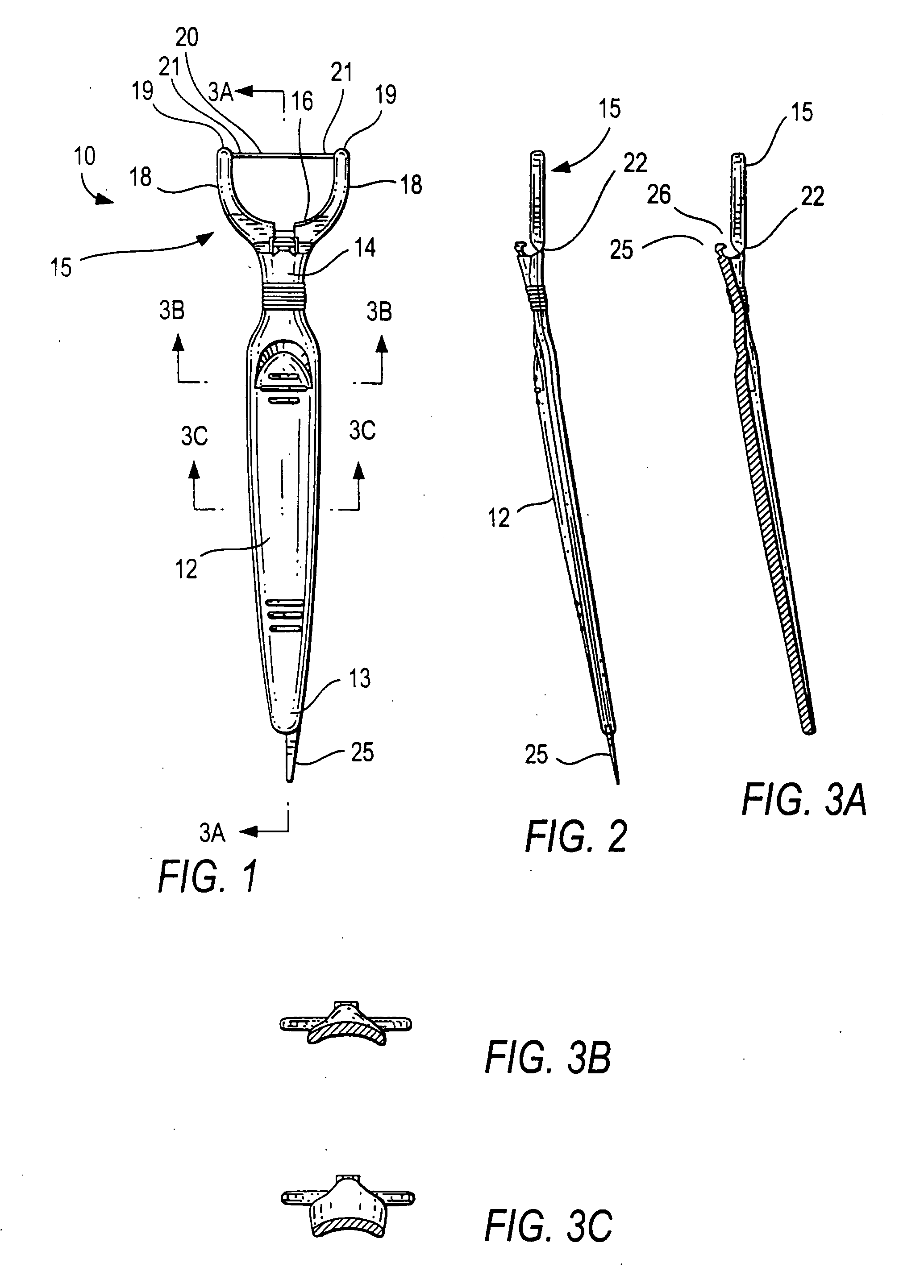
[0061] FIGS. 2 shows that the flosser head portion 15 is connected to the handle 12 by a living hinge 22 which is a thin portion of the injection molded plastic having thickness of approximately 0.012 inches.

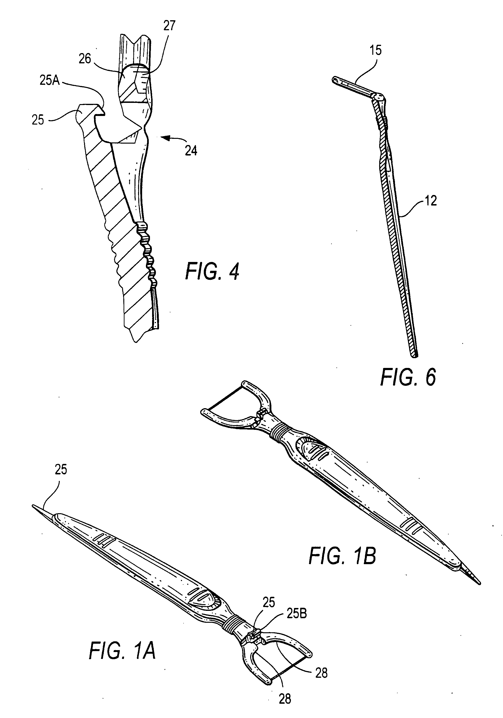
[0062] This flosser is typically packaged in the flat state as seen in FIGS. 1, 2, 3, 1A and 1B. For use, the flosser head portion 15 is pivoted relative to the handle 12 to a final assembled position as seen in FIGS. 5 and 6 where the flosser head is moved about 700 from the generally flat plane of its initial state, however this angle...


PUM


Abstract

A dental flossing device formed of: a. a handle having proximal and distal ends, b. a flosser head extending from the distal end of the handle, the flosser head comprising a base, two spaced apart arms extending from the base and having distal ends, and a strand of dental floss extending between and secured to the distal ends of the arms, c. a hinge connecting the distal end of the handle to the flosser head, the flosser head having a first position generally co-planar with the handle, the flosser head being bendable about the hinge to a second position that is angled relative to the handle, the arms in the first position of the flosser head being spaced apart a first distance, d. the device including engagement means for securing the flosser head in the second position and urging the distal ends of the arms to be spaced apart a second distance greater than the first distance to thus stretch the strand of dental floss to be more taut.

Description

[0001] This application claims benefit of the Sep. 15, 2003 filing date of applicant's prior U.S. Provisional Patent Application No. 60 / 503,618 and the Feb. 6, 2004 filing date of applicant's prior Provisional Patent Application No. 60 / 542,534.BACKGROUND OF THE INVENTION [0002] 1. Field of the Invention [0003] This invention is in the field of dental floss holders where a small segment or strand of dental floss is secured between two spaced apart arms which extend from a handle which include dental flossers which are essentially flat, dental flossers having the flosser head bent relative to the handle, and dental flossers having a replaceable flosser head. RELATED INVENTIONSU.S. Pat. No.InventorDate4,006,750I. S. ChodorowFeb. 8, 19774,016,892I. S. ChodorowFeb. 8, 1977D 244,376I. S. ChodorowMay, 1977D 250,214I. S. ChodorowNov. 7, 1978D 301,071R. FranchiMay 9, 19895,086,792I. S. ChodorowFeb. 11, 19925,538,023I. S. ChodorowJul. 23, 19965,829,458I. S. ChodorowNov. 3, 19986,065,479I. S....

Claims


Application Information

Patent Timeline
Patent Type & Authority Applications(United States)
IPC IPC(8): A61C15/04A61C15/00
CPCA61C15/046
Inventor CHODOROW, IMGRAMSALMON, SCOTT
Owner RANIR LLC
Why Eureka
Try Eureka