

Cutting insert
a cutting edge and insert technology, applied in the field of cutting inserts, can solve the problems of reducing the cutting resistance of the cutting insert, and achieve the effects of preventing damage and adhesion due to heat at the front cutting edge in the vicinity of the corner portion, extending the tool life of the cutting insert, and lubricating and cooling efficiently
- Summary
- Abstract
- Description
- Claims
- Application Information
AI Technical Summary
Benefits of technology
Problems solved by technology
Method used
Image

Examples
Embodiment Construction
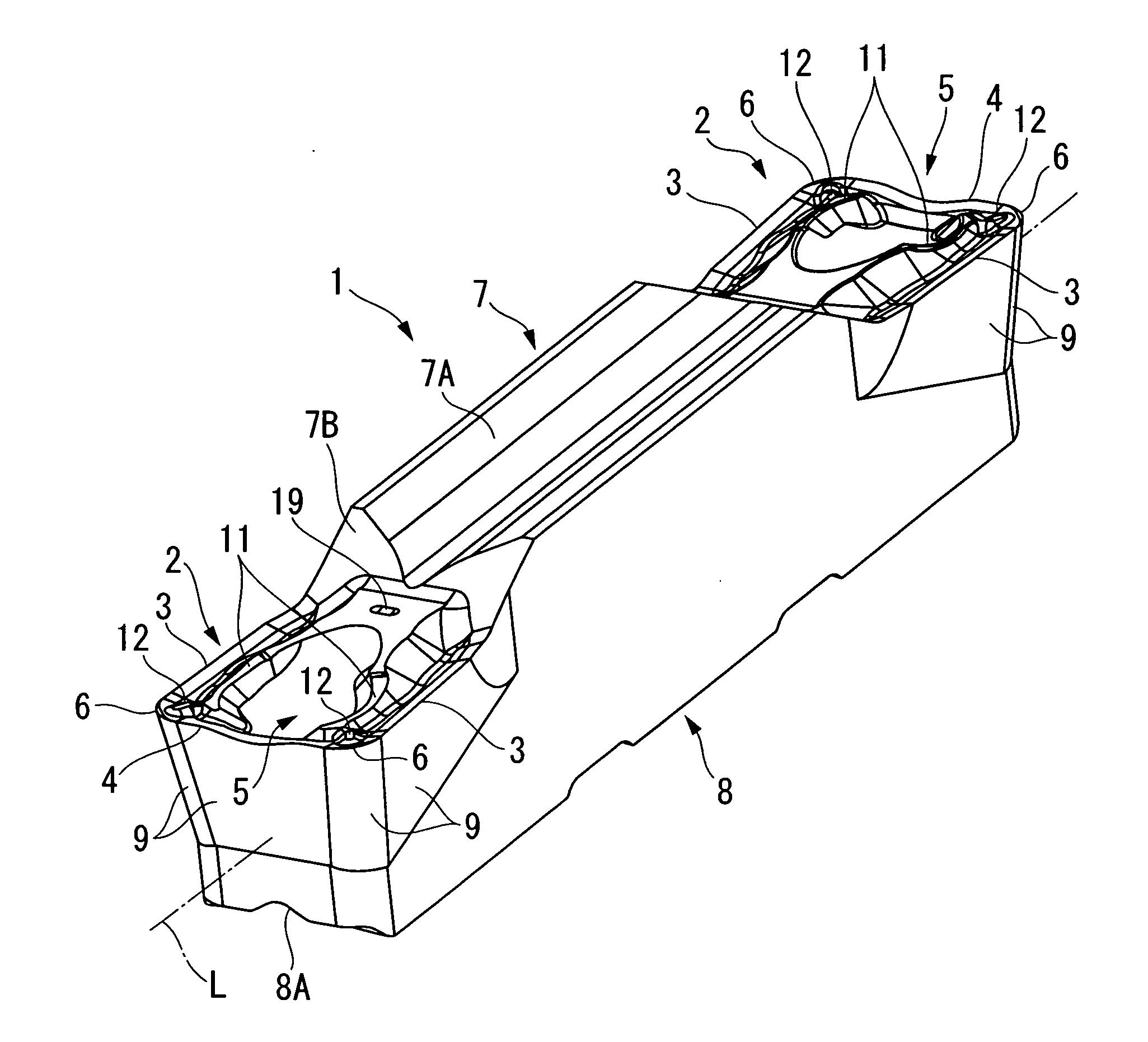
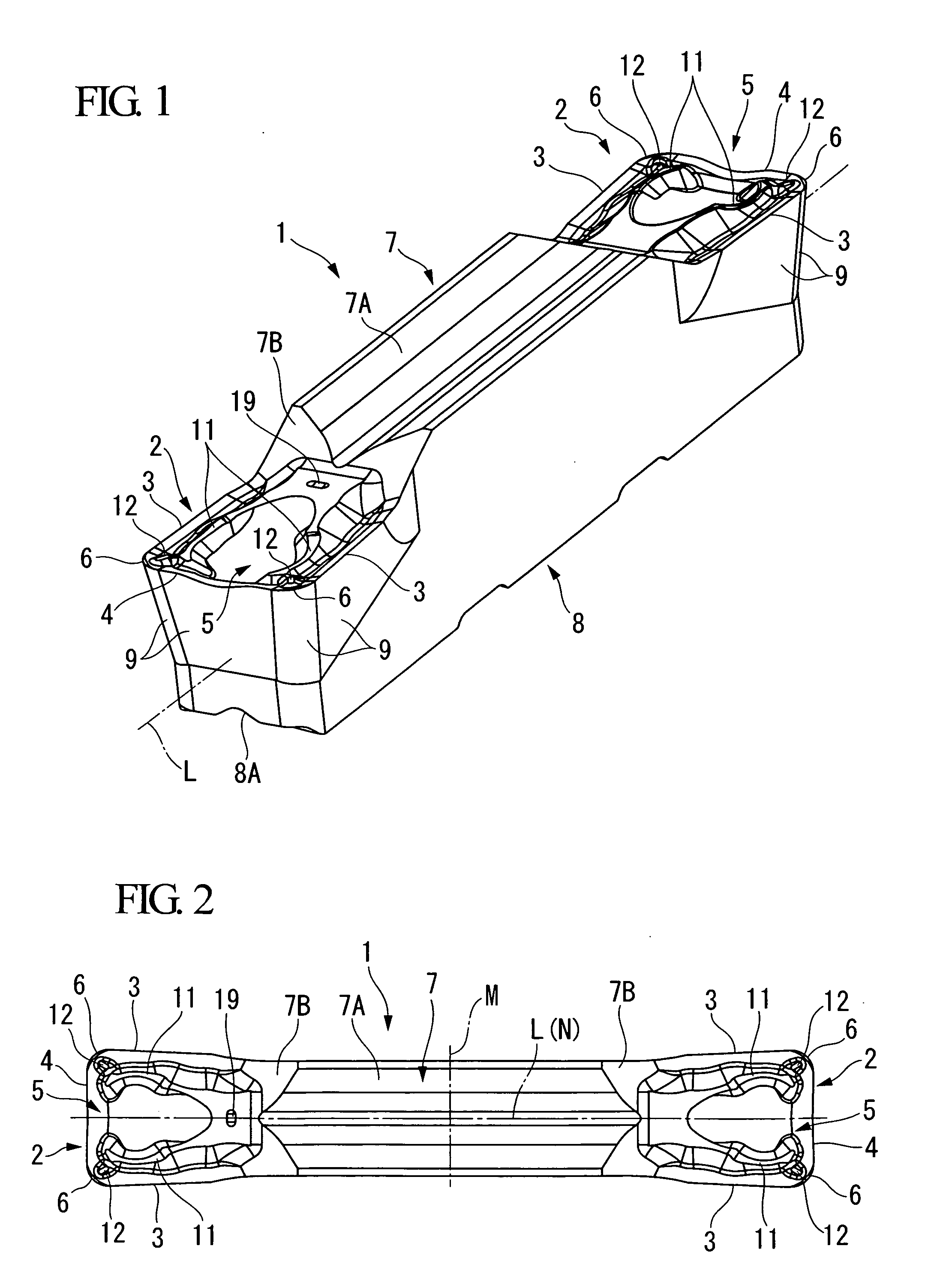
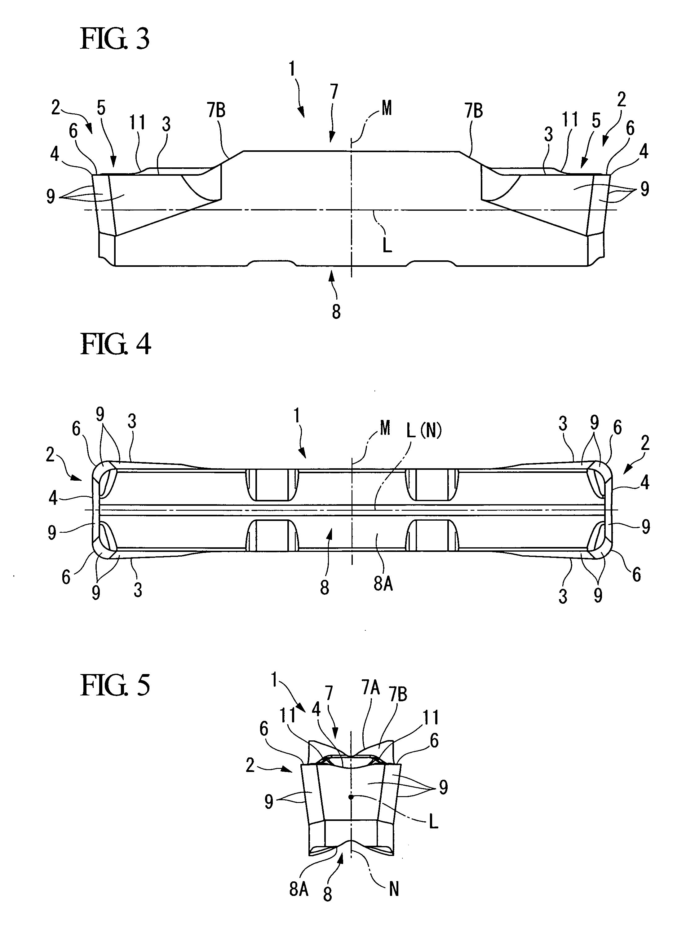
[0062]FIGS. 1 to 8 show a first embodiment of a cutting insert according to the present invention. An insert body 1 of the present embodiment is formed from a hard material such as cemented carbide or the like, and has substantially a square shaft shape (a square pillar shape) extending along an axis L. The insert body 1 is formed so as to substantially be symmetrical about a plane M perpendicular to the axis L at a center in a longitudinal direction (i.e. the axis L direction; in other words, left and right direction of FIGS. 2 to 4) of the insert body 1. Further, the insert body 1 is formed so as to be symmetrical about a plane N at a center of a width direction (i.e. an up and down direction in FIGS. 2 and 5, and a left and right direction in FIG. 5) of the insert body 1. The plane N is perpendicular to the plane M, includes the axis L, and extends in a thickness direction (i.e. an up and down direction in FIGS. 3 and 5) of the insert body 1.
[0063]A cutting edge portion 2 is form...
PUM
| Property | Measurement | Unit |
|---|---|---|
| angle | aaaaa | aaaaa |
| angle | aaaaa | aaaaa |
| angle | aaaaa | aaaaa |
Abstract
Description
Claims
Application Information