Projection display apparatus

a technology of projection display and display device, which is applied in the direction of static indicating device, optical radiation measurement, instruments, etc., can solve the problems of difficulty in ensuring the amount of light needed for a projection display apparatus only with a single deterioration of solid state light source, so as to reduce the amount of light

Active Publication Date: 2008-10-09
SANYO ELECTRIC CO LTD
View PDF7 Cites 32 Cited by
  • Summary
  • Abstract
  • Description
  • Claims
  • Application Information

AI Technical Summary

Benefits of technology

[0019]In the above-described aspects, the projection display apparatus further includes a calculation unit (deterioration rate calculator 240) configured to calculate a deterioration rate of the measurement target light source in accordance with the result of the comparison between the amount of light of the measurement target light source acquired by the acquisition unit, and the reference amount of light. The light source controller controls the amount of light of the solid state light source hav

Problems solved by technology

Meanwhile, it is difficult to secure an amount of light necessary for a projection display apparatus only with a single solid state light source.
In the meantime, there is a case that a solid state light source deteriorates due to a change in ambient temperature of a solid state light source.
Additionally, there is also a case that the solid state light source deteriorates with time.
Hence, the number of the sensors increases with an increase in the number of the light sources, and this leads

Method used


Image

  • Projection display apparatus
  • Projection display apparatus
  • Projection display apparatus

Examples


first embodiment

(Configuration of a Projection Display Apparatus)

[0035]A configuration of a projection display apparatus according to a first embodiment will be described below with reference to the accompanying drawings. FIG. 1 is a schematic view showing a configuration of a projection display apparatus 100 of a first embodiment.

[0036]As shown in FIG. 1, the projection display apparatus 100 includes: array light sources 10 (an array light source 10R, an array light-source 10G, and an array light source 10B) in which plurality of solid state light sources 11 (solid state light sources 11R, solid state light sources 11G, and solid state light sources 11B) are disposed in an array; light valves 80 (a light valve 30R, a light valve 30G, and a light valve 30B); a cross dichroic prism 50; and a projection lens unit 90 provided with a light amount sensor 70 is provided.

[0037]Meanwhile, it should be noted that an optical element (for example, a taper rod or a fly eye lens), which uniformizes light emitte...

second embodiment

[0086]A second embodiment of the present invention will be described below with reference to the accompanying drawings. In the following description, different points between the above-mentioned first embodiment and the second embodiment will be mainly described.

[0087]In the first embodiment described above, it is not considered that an amount of light of the solid state light source 11 detected by the light amount sensor 70 is different in accordance with the disposition of the solid state light source 11. In the second embodiment, by contrast, it is considered that the amount of light of the solid state light source 11 detected by the light amount sensor 70 is different in accordance with the disposition of the solid state light source 11.

(Configuration of a Control Unit)

[0088]A configuration of a control unit according to the second embodiment will be described below with reference to the accompanying drawings. FIG. 5 is a block diagram showing a configuration of a control unit 2...

third embodiment

[0103]A third embodiment of the present invention will be described below with reference to the accompanying drawings. In the following description, different points between the above-mentioned first embodiment and the third embodiment will be mainly described.

[0104]In the first embodiment described above, a deterioration rate of a measurement target light source is calculated in the turn-on phase and the turn-off phase. In the third embodiment, in the meantime, the deterioration rate of the measurement target light source is calculated in a back light control in which an amount of light of the array light source 10 is switched in response to an image input signal.

(Configuration of a Control Unit)

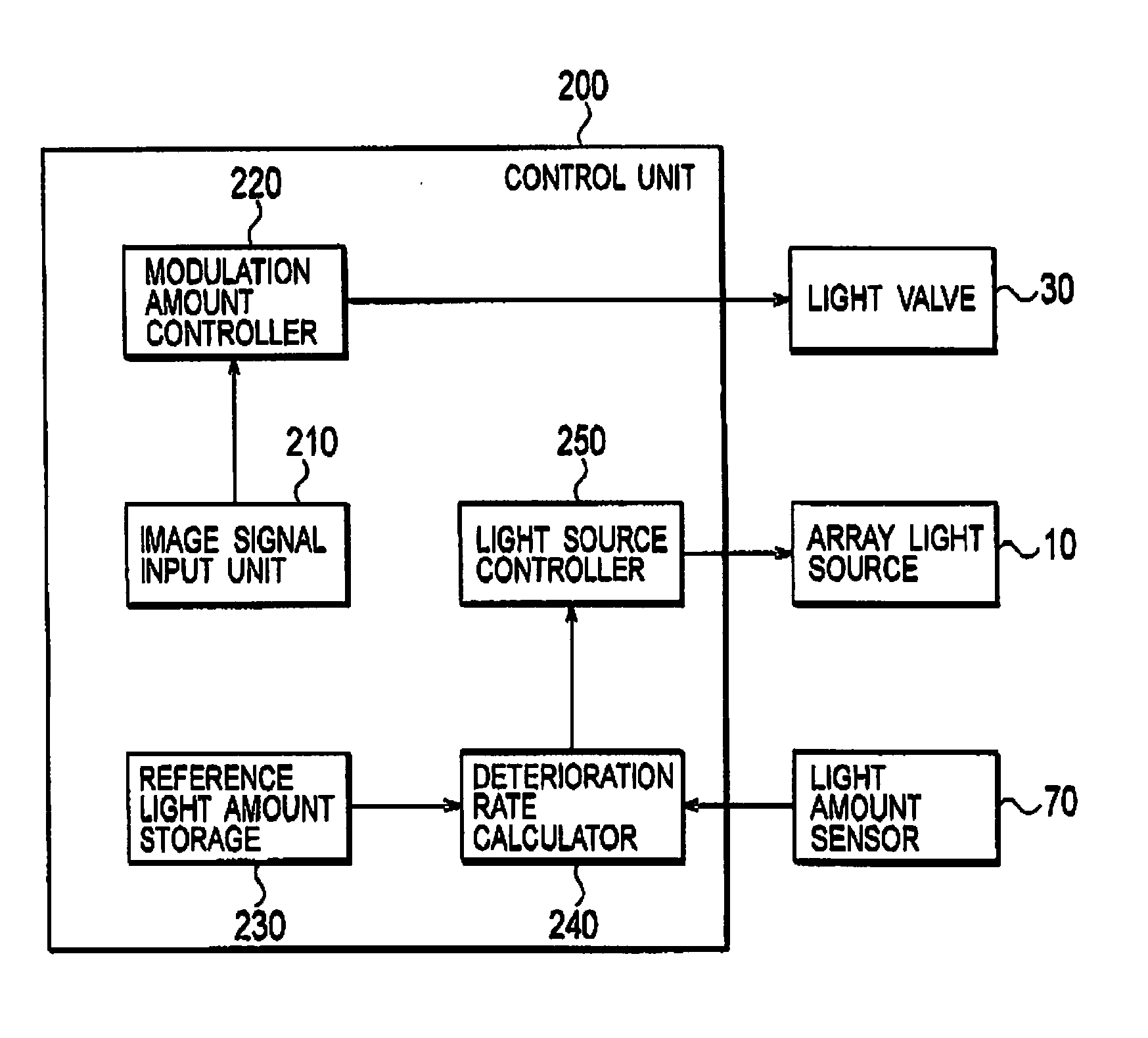
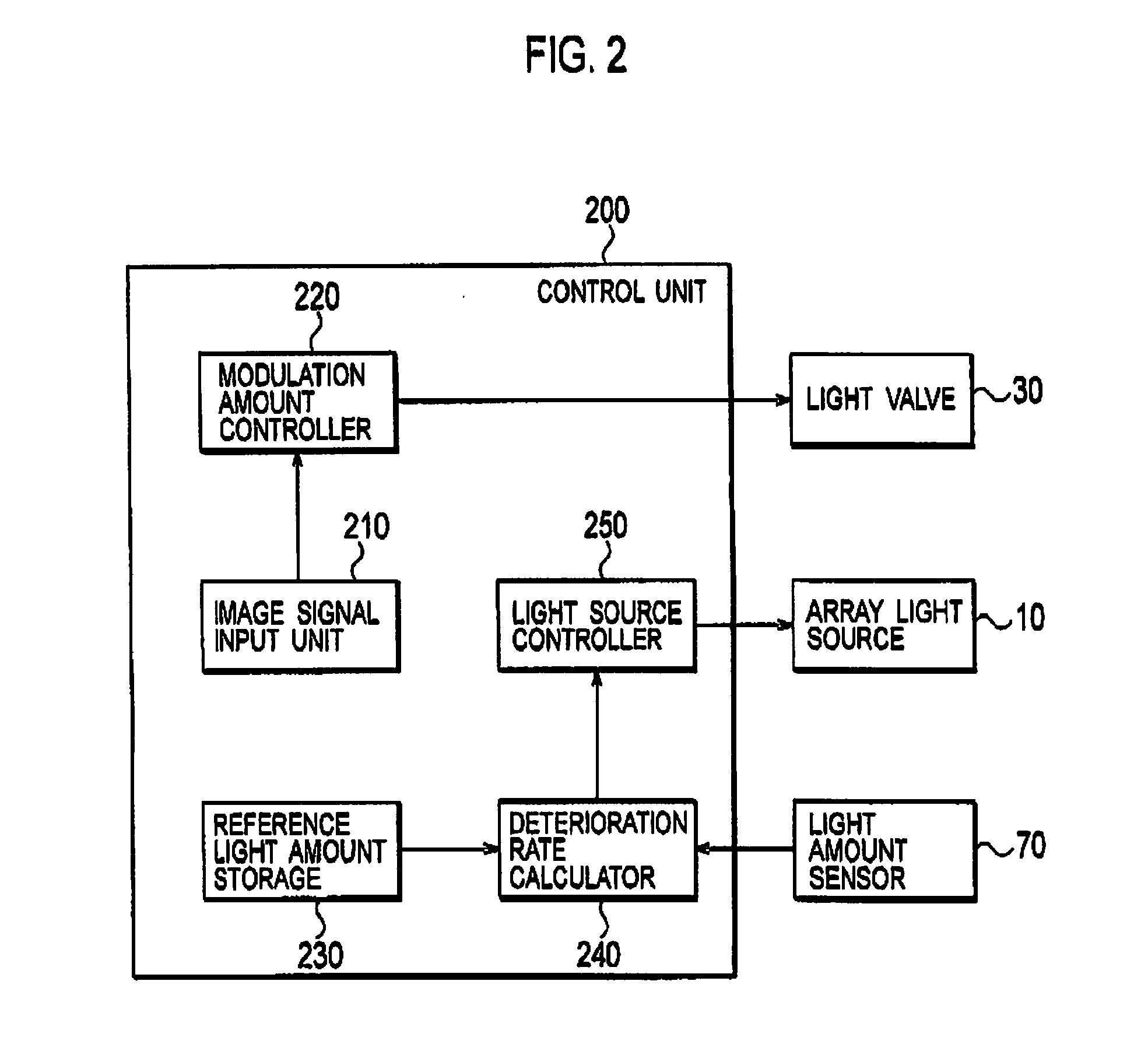
[0105]A configuration of a control unit according to the third embodiment will be described below with reference to the accompanying drawings. FIG. 7 is a block diagram showing a configuration of a control unit 200 of the third embodiment. It should be noted that in FIG. 7, constituent elem...


PUM


Abstract

A projection display apparatus includes: a light amount sensor which detects an amount of light emitted from an array light source; a deterioration rate calculator which acquires an amount of light of a measurement target light source from the amount of light detected by the light amount sensor; a reference light amount storage which stores a reference amount of light of an amount of light emitted from plurality of solid state light sources, for each of the solid state light sources; and a light source controller which controls the amount of light emitted from the plurality of solid state light sources for each of the solid state light sources, and the deterioration rate calculator determines whether the measurement target light source has deteriorated, in accordance with a result of a comparison between the amount of light detected by the light amount sensor, and the reference amount of light.

Description

BACKGROUND OF THE INVENTION[0001]1. Field of the Invention[0002]The present invention relates to a projection display apparatus including an array light source in which plurality of solid state light sources are disposed in an array.[0003]2. Description of the Related Art[0004]Projection display apparatuses have heretofore been known, each of which includes a light valve (a liquid crystal panel or the like) modulating light emitted from a light source. A projection display apparatus projects light modulated by a light valve on a screen. Further, as a light source provided to a projection display apparatus, an attempt has been made to employ a solid state light source such as a laser diode or an LED.[0005]Meanwhile, it is difficult to secure an amount of light necessary for a projection display apparatus only with a single solid state light source. For this reason, in a projection display apparatus, a plurality of solid state light sources are normally disposed in an array.[0006]In t...

Claims


Application Information

Patent Timeline
IPC IPC(8): G03B21/14H05B44/00
CPCG03B21/14G09G3/002G09G2320/0233G09G2320/043G09G2320/0626G09G2320/0646G09G2330/021G09G2360/145G09G2360/16H04N9/3155H04N9/3194H04N9/3197H05B41/38G03B21/2053
Inventor INOUE, MASUTAKATSUCHIYA, SEIJITANASE, SUSUMUHIRANUMA, YOSHINAOABE, TAKAAKIHARAGUCHI, MASAHIRO
Owner SANYO ELECTRIC CO LTD
Why Eureka
Try Eureka