Input-output circuit, recording apparatus and reproduction apparatus for digital video signal

a digital video signal and output circuit technology, applied in the field of transmission receiving techniques and recording reproduction techniques of signals, can solve the problems of large cost of high-efficiency digital compressors used in broadcasting stations for each vtr, and the technique for recording the digital signal thus transmitted is not yet disclosed, so as to achieve secure time interval of packet signals so as to be transmitted, and stable reproduction of digital signals

Inactive Publication Date: 2008-11-27
MAXELL HLDG LTD
View PDF60 Cites 0 Cited by
  • Summary
  • Abstract
  • Description
  • Claims
  • Application Information

AI Technical Summary

Benefits of technology

[0010]An object of the present invention is to provide an apparatus capable of efficiently recording and reproducing signals compressed according to the MPEG standard, for example, and transmitted.
[0011]Another object of the invention is to provide a receiving apparatus and a recording-reproduction apparatus for digital broadcast and a low-cost interfacing circuit.
[0012]Still another object of the present invention is to provide an digital signal input-output circuit which can meet any difference in the transmission rate or the format of the recording signal.
[0019]Furthermore, in reproducing the signal recorded this way, the reproduced signal is temporally adjusted in accordance with the clock signal generated by a local oscillator, and the time interval of packet signals thus can be securely restored. Also, the rotation of the rotary head is controlled by use of the particular clock signal, whereby any overage or shortage between a reproduced signal and an output signal is eliminated, thereby realizing a stable reproduction of digital signals.

Problems solved by technology

In the case of digital broadcasting, however, a high-efficiency digital compression is already employed, and therefore, the decompression and digital recording of the signal as disclosed in the aforementioned publication JP-A-1-258255 fails to obtain a sufficient compression efficiency, or the use of such a high-efficiency digital compressor as used in broadcasting stations for each VTR has a great cost.
Nevertheless, any technique for recording the digital signal thus transmitted is not yet disclosed.

Method used


Image

  • Input-output circuit, recording apparatus and reproduction apparatus for digital video signal
  • Input-output circuit, recording apparatus and reproduction apparatus for digital video signal
  • Input-output circuit, recording apparatus and reproduction apparatus for digital video signal

Examples


Embodiment Construction

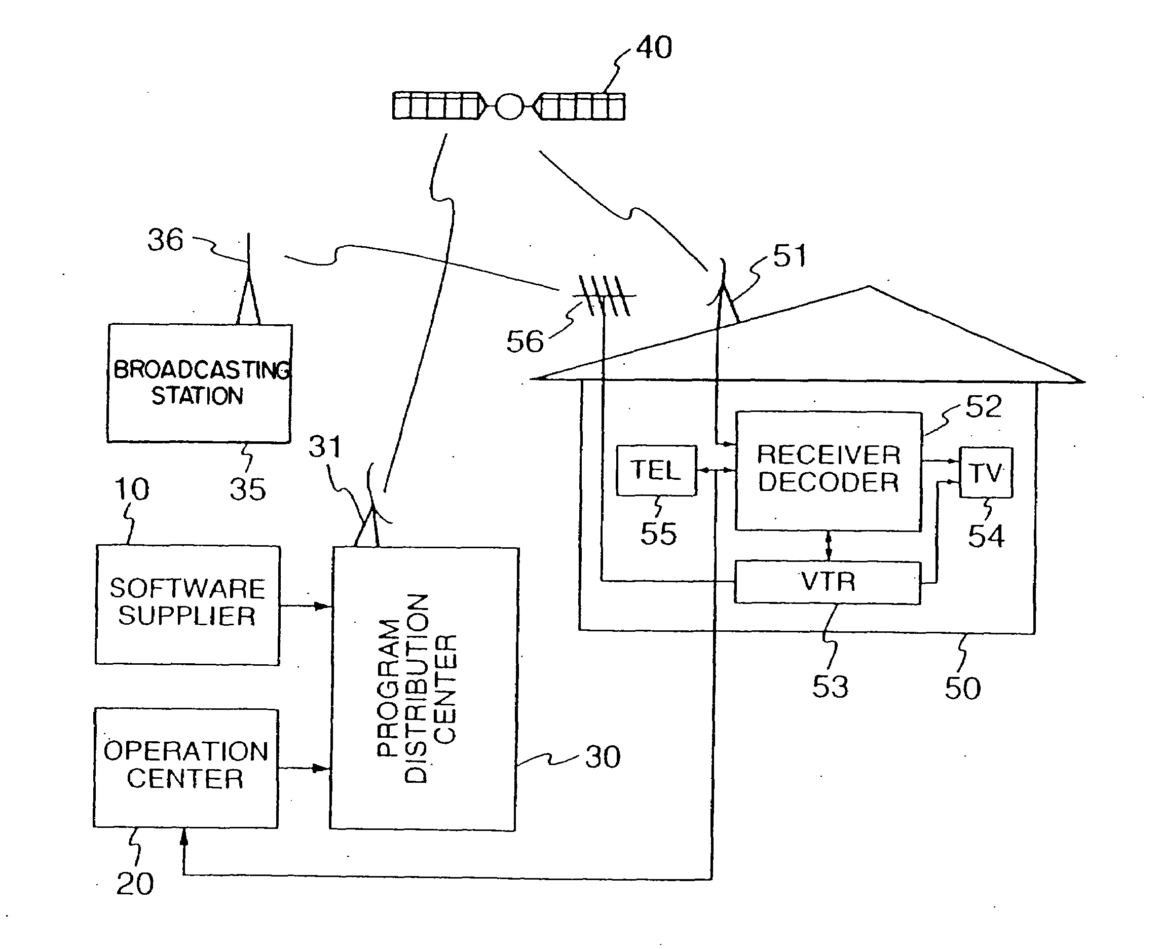
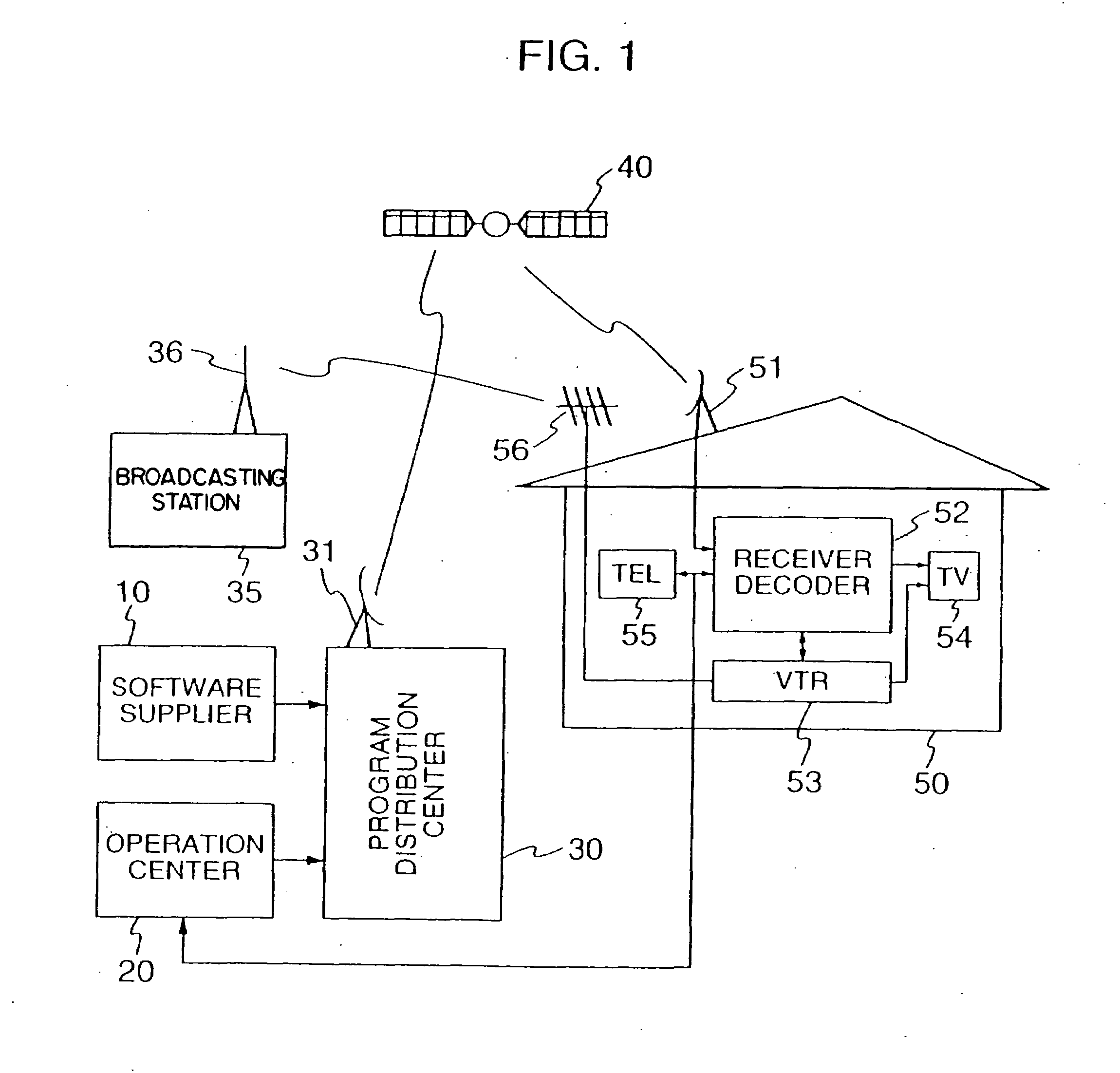
[0051]A video distribution service using a satellite according to an embodiment of the invention will be described with reference to FIG. 1. In FIG. 1, a reference numeral 10 designates a software supplier, numeral 20 an operation center, numeral 30 a program distribution center, numeral 31 a transmitter, numeral 35 a current broadcasting station, numeral 36 a transmitter, numeral 40 an artificial satellite for distributing signals, numeral 50 a subscriber household, numeral 51 a receiver, numeral 52 a receiver decoder, numeral 53 a VTR, numeral 54 a TV receiver, numeral 55 a telephone set, and numeral 56 a receiver.

[0052]The video distribution service is carried out by an operator managing the operation center 20. The operator signs a contract with the software supplier 10 and causes the required software to be supplied from the software supplier 10 to the program distribution center 30. According to the embodiment shown in FIG. 1, only one supplier 10 is shown. Normally, however, ...


PUM

PropertyMeasurementUnit
lengthaaaaaaaaaa
timeaaaaaaaaaa
compression ratioaaaaaaaaaa

Abstract

A video signal input-output circuit and a recording-reproduction apparatus in which a digitally compressed video signal input in packet form can be recorded and reproduced efficiently and in stable fashion. In this apparatus, a clock reference is detected from a packet signal containing the clock reference and a digitally compressed video signal, a time stamp for a packet is generated using a clock signal in phase with the clock reference and added to the particular packet, and the packet signals with the time stamp added thereto are recorded closely to each other in a data storage element such as a magnetic recording medium. At playback, the packet interval is output by being restored to the original length on the basis of the time stamp added to the packet in store.

Description

[0001]The present application is a continuation of application Ser. No. 11 / 936,852, filed Nov. 8, 2007; which is a continuation of application Ser. No. 10 / 367,730, filed Feb. 19, 2003, now U.S. Pat. No. 7,319,808; which is a continuation of application Ser. No. 09 / 455,413, filed Dec. 6, 1999, now U.S. Pat. No. 6,600,870; which is a divisional application of Ser. No. 08 / 972,457, filed Nov. 18, 1997, now U.S. Pat. No. 6,041,161; which is a divisional application of Ser. No. 08 / 547,662, filed Oct. 24, 1995, now abandoned, the contents of which are incorporated herein by reference.BACKGROUND OF THE INVENTION[0002]The present invention relates to transmission-receiving techniques and recording-reproduction techniques for signals between apparatuses, or more in particular to an output circuit, a recording apparatus and a reproduction apparatus for digital video signals, in which the digital information signal for moving pictures, programs or the like transmitted by transmission means such...

Claims


Application Information

Patent Timeline
Patent Type & Authority Applications(United States)
IPC IPC(8): H04N7/26H04N5/91G11B15/087G11B15/467G11B15/473G11B15/52G11B20/12G11B20/18G11B27/00G11B27/032G11B27/30H04B7/185H04L12/64H04N5/76H04N5/775H04N5/781H04N5/913H04N5/92H04N7/10H04N7/167H04N7/173H04N9/79H04N9/804H04N9/82H04N9/877
CPCG11B15/087G11B15/4731G11B15/52G11B20/1211G11B20/1813G11B27/005G11B27/032G11B27/3027G11B27/3036G11B27/3063G11B2220/90G11B2220/91H04B7/18523H04L12/64H04N5/775H04N7/106H04N7/1675H04N7/173H04N9/7921H04N9/8042H04N9/8233H04N9/877H04N2005/91321H04N21/4325H04N21/4334G11B20/10
Inventor OKAMOTO, HIROOHOSOKAWA, KYOICHIOWASHI, HITOAKITACHIBANA, HIROAKINOGUCHI, TAKAHARU
Owner MAXELL HLDG LTD
Why Eureka
Try Eureka