Ophthalmologic Instrument

a technology of ophthalmologic instruments and ophthalmologic instruments, which is applied in the field of ophthalmologic instruments, can solve the problems of distortion in the photographed reflection image, the change of the reflection image photographed by the imaging device, etc., and achieve the effect of accurately and efficiently evaluating the change over time in the lacrimal layer

Inactive Publication Date: 2008-12-18
TOMEY CORP
View PDF4 Cites 16 Cited by
  • Summary
  • Abstract
  • Description
  • Claims
  • Application Information

AI Technical Summary

Benefits of technology

[0028]With such a structure, an image photographed immediately after the blinking of the eye can be set as the reference image, thus the change over time in the lacrimal layer is accurately...

Problems solved by technology

When the state of the lacrimal layer changes, the reflection image photographed by t...

Method used


Image

  • Ophthalmologic Instrument
  • Ophthalmologic Instrument
  • Ophthalmologic Instrument

Examples


Embodiment Construction

[0041]An explanation will be given below of an opthalmologic apparatus (cornea topographer) according to one embodiment of the present invention.

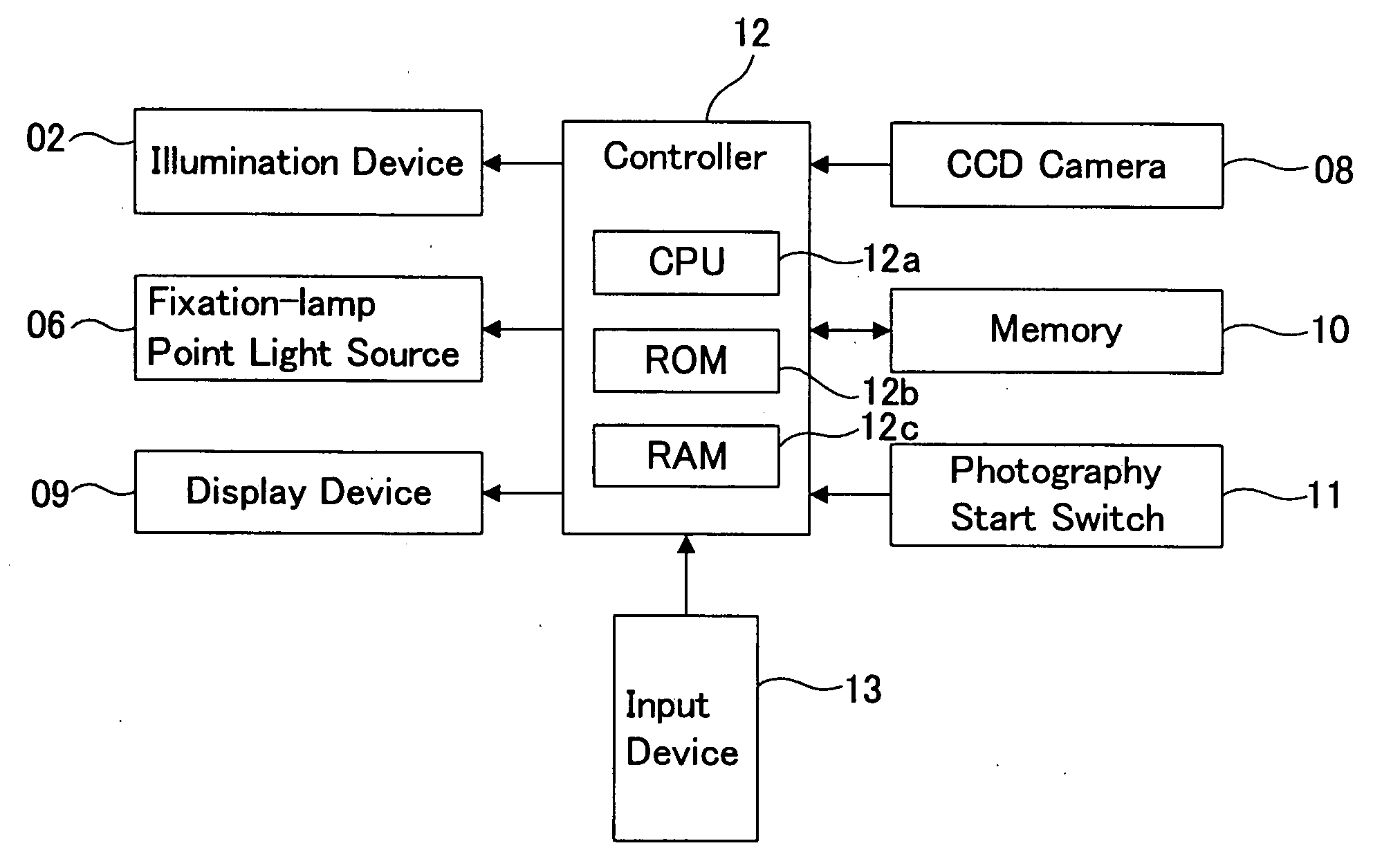
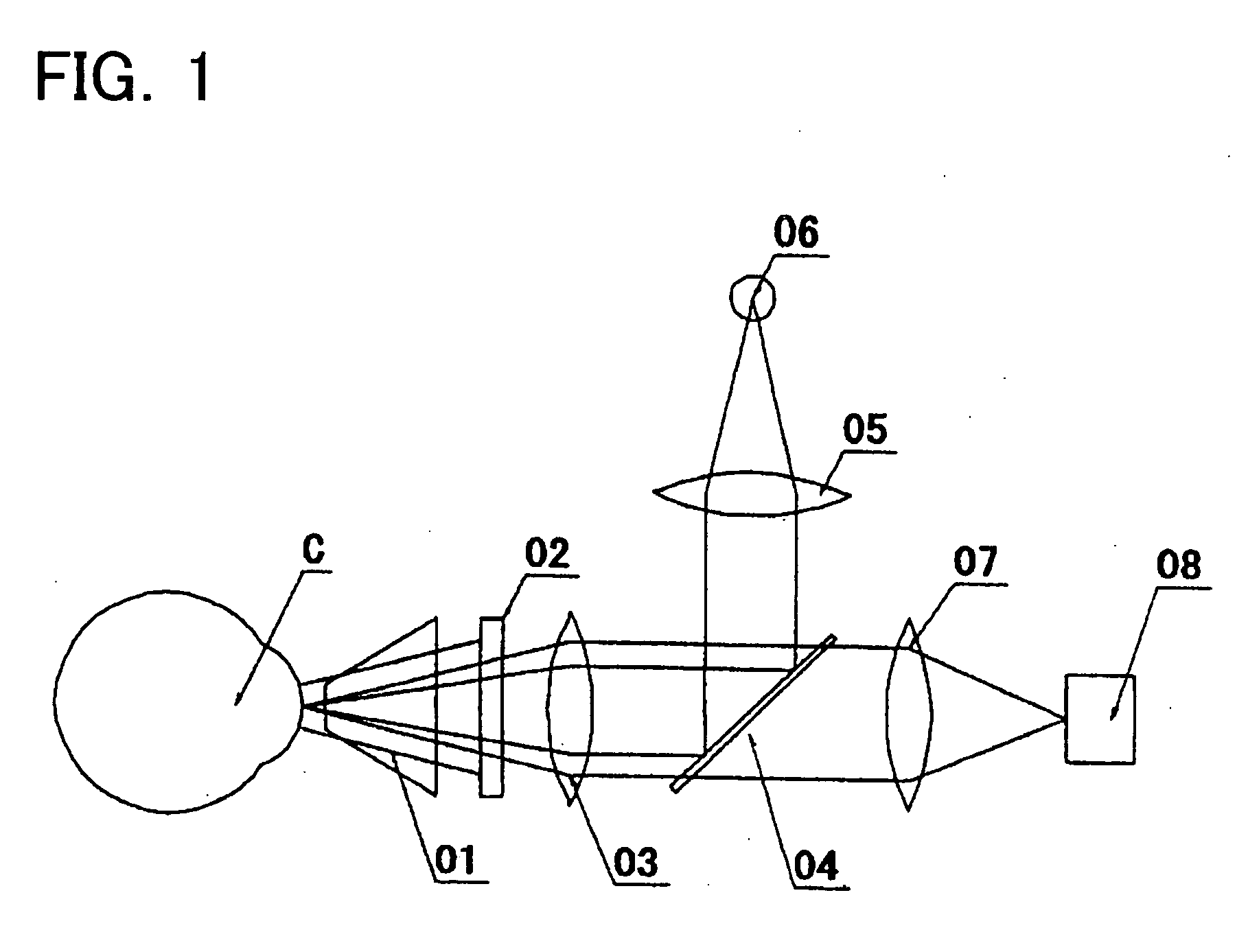
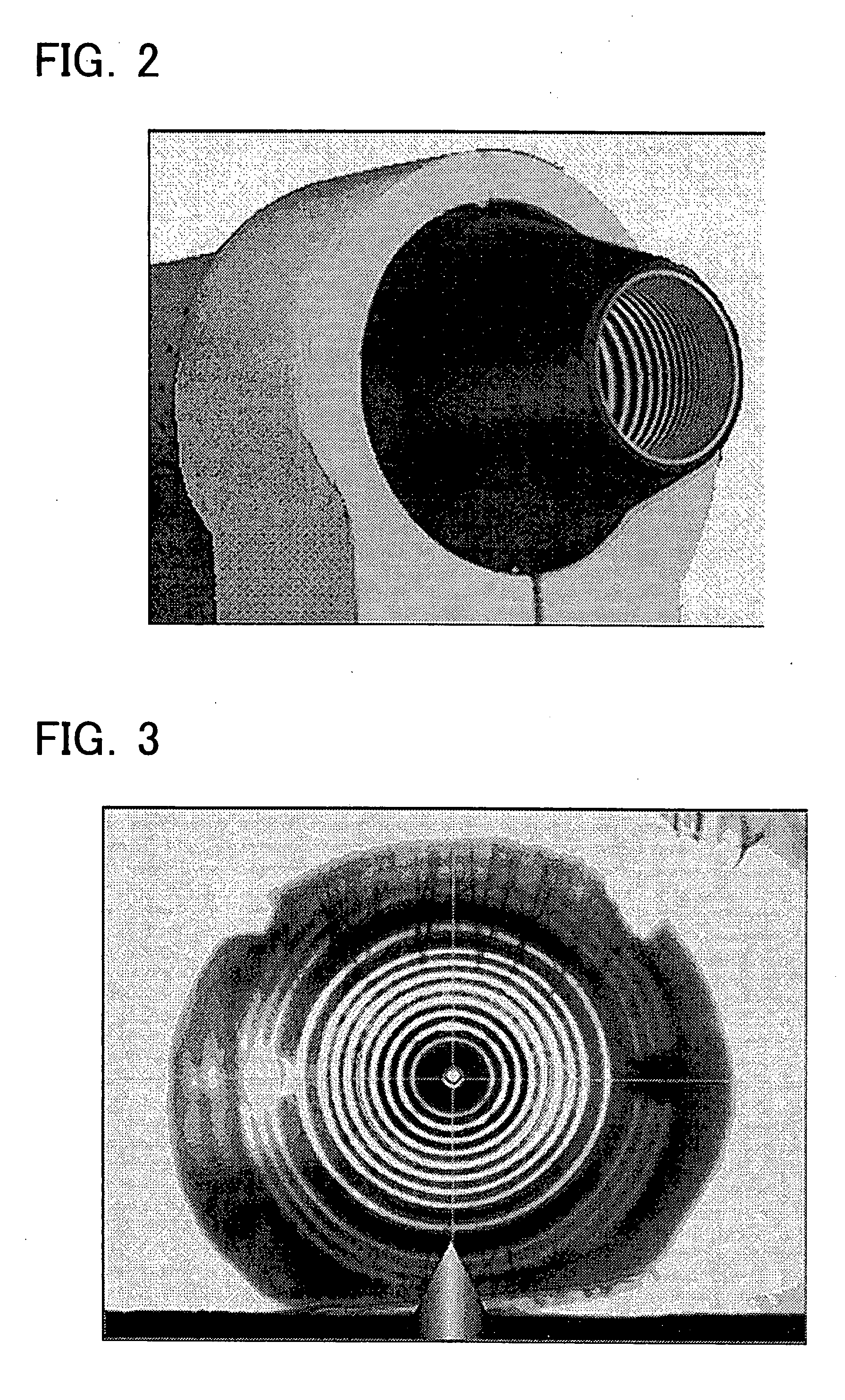
[0042]As shown in FIG. 1, the opthalmologic apparatus of the present embodiment comprises a cone (01) which is disposed so as to face the cornea of an eye to be examined C, and an illumination device (02) (for example, an LED) disposed on the back surface of the cone (01). As shown in FIG. 2, the inner portion of the cone (01) is a hollow conical cylinder, and is formed from a transparent resin. A transparent film with a concentric circular pattern printed thereon is attached to the inner wall of the cone (01). The outer wall of the cone (01) has a coating applied that reflects light. Thus the illumination light from the illumination device (02) disposed on the back surface of the cone (01) is scattered inside the cone (01), and a portion of the light is blocked by the transparent film attached to the inner wall of the cone (01), and that p...


PUM


Abstract

The present invention provides an opthalmologic apparatus that can noninvasively measure the state of the lacrimal layer formed on the cornea surface and that can quantitatively measure the state of the lacrimal layer without utilizing a reflection image from the retina.
The opthalmologic apparatus according to the present invention comprises an optical projection system for projecting light of a specified pattern onto a cornea surface, and an imaging device for photographing a reflection image of the projected light from the cornea surface. An operating unit calculates the degree of distortion of the reflection image on the basis of the density value distribution of the image photographed by the imaging device. The operating unit can determine the state of the lacrimal layer using the calculated degree of distortion.

Description

TECHNICAL FIELD[0001]The present invention relates to an opthalmologic apparatus. More specifically, the present invention relates to an opthalmologic apparatus that can evaluate the state of a lacrimal layer formed on a cornea surface.BACKGROUND ART[0002]A keratometer and a corneal topographer are known as opthalmologic apparatuses for observing and measuring a cornea surface and the shape thereof. Generally these types of opthalmologic apparatuses project light of a desired pattern onto the cornea surface. Then the state of the cornea surface, shape of the cornea, or other characteristic is measured by observing, photographing and analyzing a reflection image of the light pattern from the cornea surface.[0003]The cornea surface is normally covered with a lacrimal fluid to form a lubricous fluid layer (lacrimal layer) on the cornea surface. The lacrimal layer gradually becomes thinner during the time the eyelid remains open after blinking and is eventually eliminated. When one's ga...

Claims


Application Information

Patent Timeline
IPC IPC(8): A61B3/14
CPCA61B3/101
Inventor HARA, NAOKOKATAOKA, HISASHIKATO, CHIHIRO
Owner TOMEY CORP
Why Eureka
Try Eureka